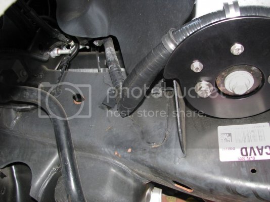
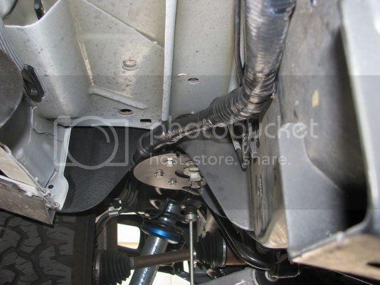
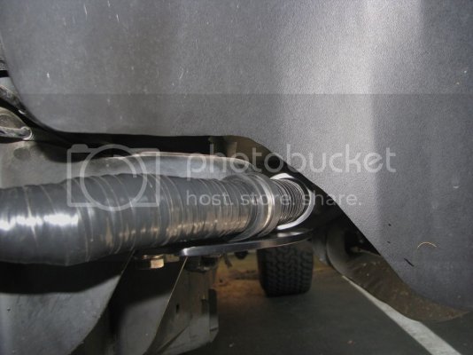
Wiring harness re-route

Disclaimer: Links on this page pointing to Amazon, eBay and other sites may include affiliate code. If you click them and make a purchase, we may earn a small commission.

HAP

Full Access Member
Joined
Feb 11, 2014
Posts
855
Reaction score
485
Location
NE NC

FarFromStock

FRF Addict
Joined
Oct 12, 2011
Posts
1,378
Reaction score
1,177
Location
Chuluota, Florida

R1jamn

Full Access Member
Joined
Jun 18, 2011
Posts
401
Reaction score
299
NOTE: Photo Bucket website has gone to a fee paid service and the pics have been omitted from 3rd party hosting.
Here is a link to Google Drive that will allow you to view the pics.
These will not be in order as how I posted them in this thread. You will have to arrange them in order yourself.
It should point you in the right direction though.

Click Google Drive


This project has been at the back of my mind for the past couple of years (Thanks for the heads up KaiserM715).
Well, I finally decided to commit some time to it.
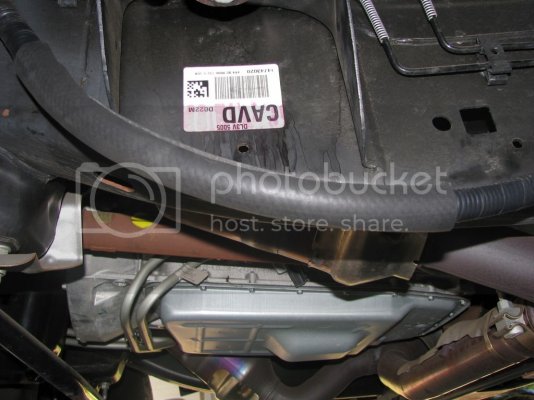
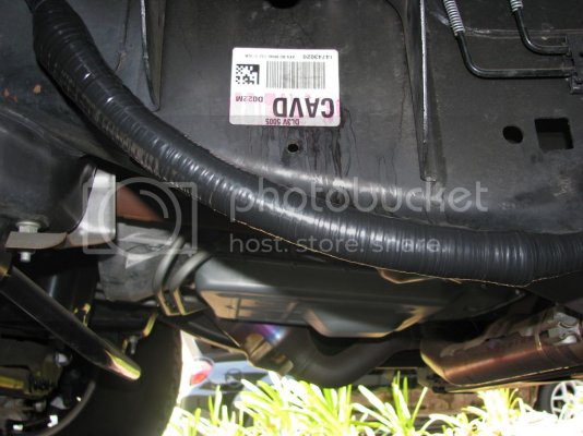
I went out to take a look up underneath the truck to see what I could engineer.
Then I gathered up some measuring tools and created a rough sketch for a relocation bracket.
This is what I conjured up.
Pics will show where I started and the stage that I am currently at.
Please be patient with me as it is not yet completed.
But stay with me as I update the process in the coming weeks.


Taking measurements and creating a sketch.
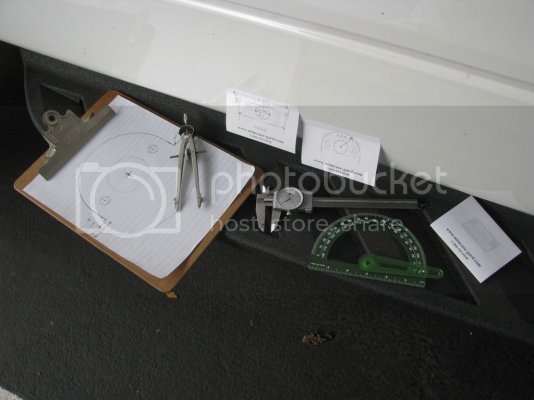
IMG_3017_zps6utad4dz.jpg

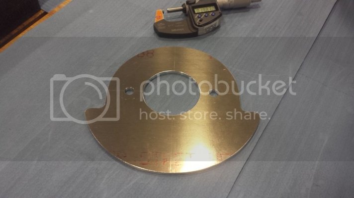
Ordered the material (7075-T6) 3/16" thickness.
This is a strong alum alloy with good corrosion resistance.
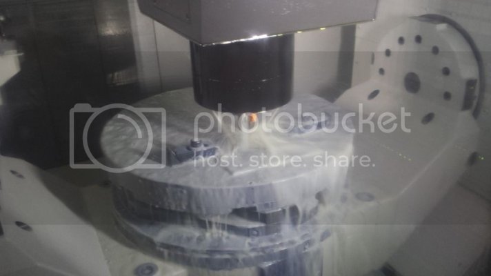
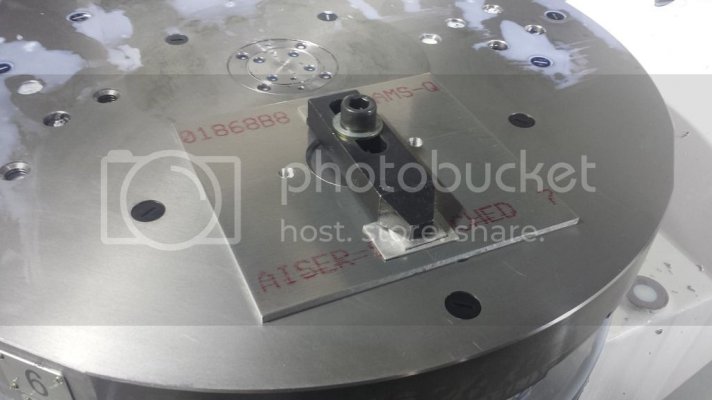
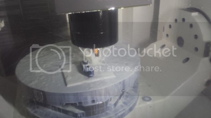
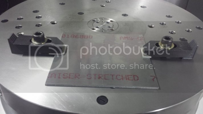
Created an NC program and set the material up on the machine table.
Milled the holes first.
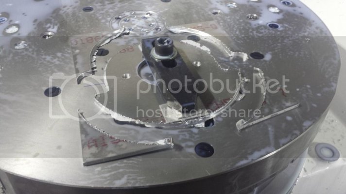
Then switched clamps and milled the periphery.
Then deburred it.
20160518_195736_zpsvmofix70.jpg

20160518_200058_zpsf1iv41e6.jpg

20160518_201339_zpsmhogcnyr.jpg

20160518_201658_zps0lyd45vg.jpg

20160518_202336_zpse19qhd1r.jpg

20160518_204508_zpsysxvwnrj.jpg

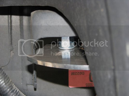
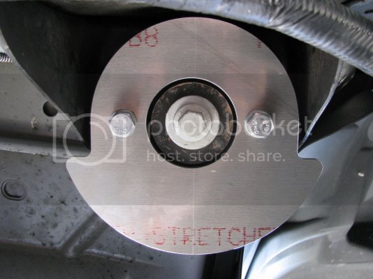
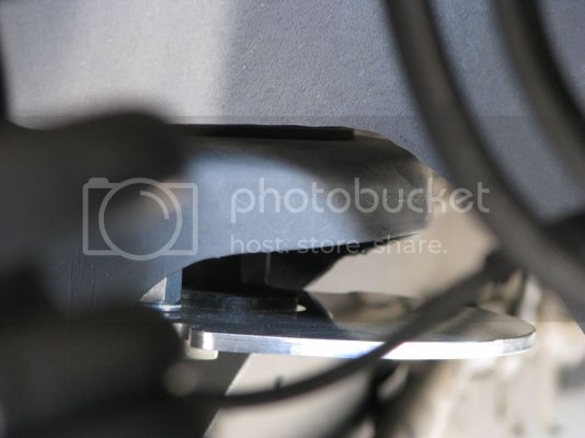
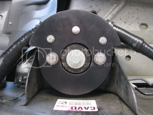
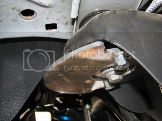
Test fitting the bracket onto the Raptor.
IMG_3021_zpsen6ly71s.jpg

IMG_3018_zpskowces6l.jpg

IMG_3027_zpsoukejaoj.jpg

IMG_3031_zpszhyjs0ke.jpg

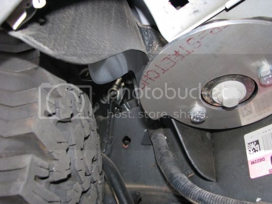
Wheel turned left at full lock to check for clearance (looks good).
IMG_3034_zpsm8infzt9.jpg

I've made changes to some of the hardware that I will be using and will be placing an order for these tonight.
I also need to get the bracket out to plating.
I'm going with hard anodizing,Type III, Class II (black) instead of powder coating.
The location of the bracket which mounts just behind the tire will throw a phalanx of rocks and debris that will soon have any powder coating chewed up.
More to come in the coming weeks.
 
Last edited:

R1jamn

Full Access Member
Joined
Jun 18, 2011
Posts
401
Reaction score
299
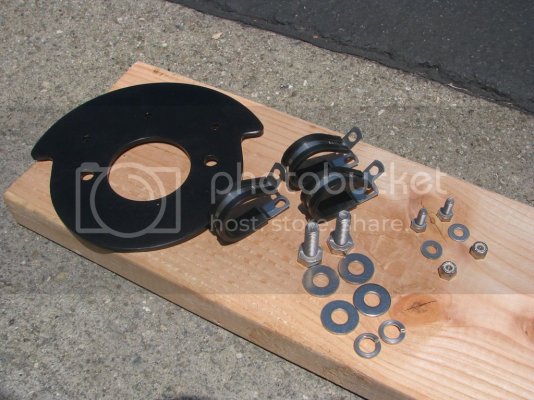
Stainless Steel hardware was ordered and has now been delivered.
The bracket is also back from plating.
It's time to assemble it!!


IMG_3067_zpsskwk6lqw.jpg

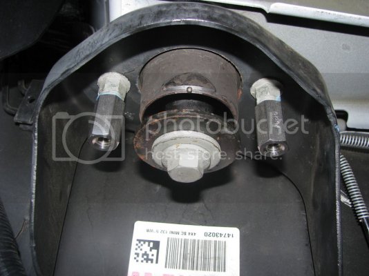
Stainless Steel Coupling Nuts (10mm x 1.5 x 30mm).

IMG_3057_zpsnqk7533r.jpg

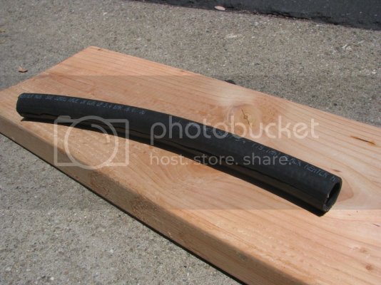
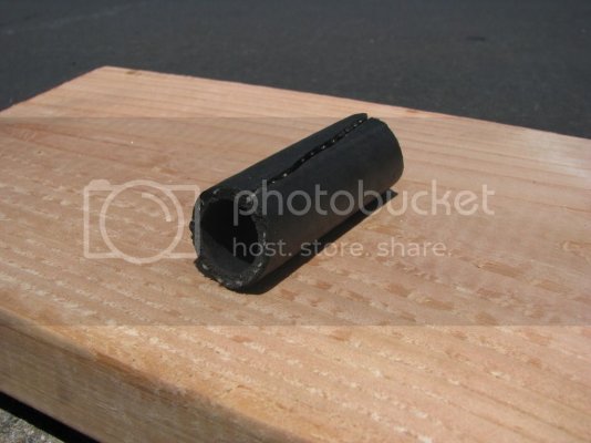
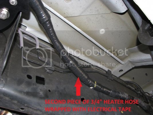
3/4" Heater Hose to cover the wire loom (2 locations) then wrapped with electrical tape.

IMG_3061_zpsr5kthasj.jpg

IMG_3070_zpsth7dfa0f.jpg

IMG_3063_zpsm1nyghqz.jpg

IMG_3064_zpsxejcc02f.jpg

Wrapped%20the%20wire%20loom_zpsokfxxuxw.jpg

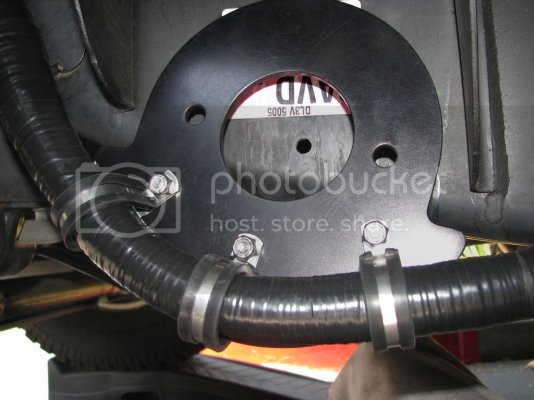
Secured the wire loom to the bracket.

IMG_3071_zps2ul5zup7.jpg

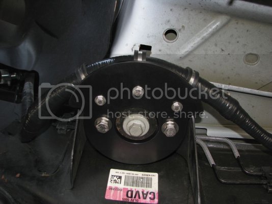
Mounted the assembly, using stainless steel hardware.

IMG_3091_zpsippix9rk.jpg

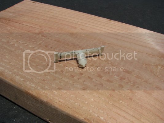
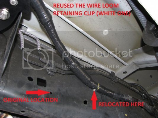
Reused the oem wire loom clip (the white one) and installed it in a new location.
FoMoCo already had another location ready to go on the frame.
I couldn't believe it....Sometimes you get lucky!

IMG_3069_zpsvkuhdnom.jpg

Reused%20wire%20loom%20clip_zpsx3dmsnby.jpg

Completed.

IMG_3080_zpstdnrkif0.jpg

IMG_3087_zpsylj79zez.jpg

IMG_3084_zpsx8eqok0s.jpg

IMG_3088_zpssvdqrowl.jpg
 
Last edited:
Top