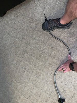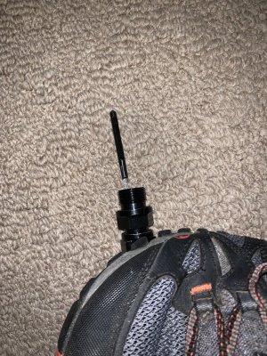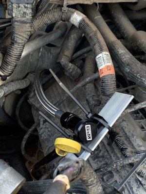
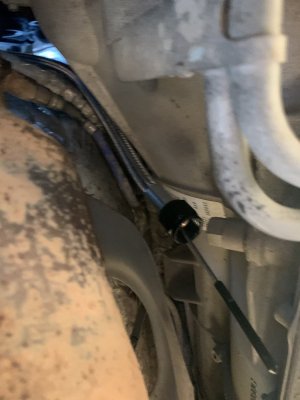
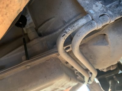
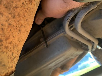
 Ok, so I had some time to mock up my dip stick install. They way I see it is there are two paths to route the dipstick tube: between the back of engine and firewall and around the side behind the exhaust. The first route is similar to the B&M video, requires some “S” bends, and better would facilitate mounting to the fire wall. The second route would yield a smoother bend radius/fewer bends, better facilitate mounting to the cam covers, but would bring the dipstick tube closer to the exhaust.
I have decided to combine the two a bit. I plan to go between the firewall and engine, but will wrap some of the dipstick with heat wrap to prevent the braided hose from damaging the existing heat insulation. I will also mount to the cam covers.
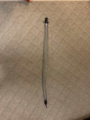
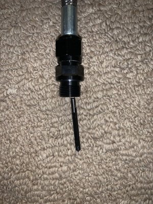
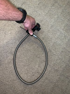
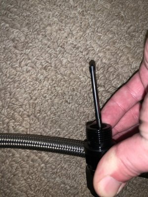
Here is a few photos of my rough in of the install. (See above) since I can only apparently figure out how to put them below the text 50% of the time.
Last edited:


