Having high beam switch control

Disclaimer: Links on this page pointing to Amazon, eBay and other sites may include affiliate code. If you click them and make a purchase, we may earn a small commission.

KryptosXLayer2

Full Access Member
Joined
Aug 29, 2017
Posts
101
Reaction score
46
Location
Charlotte, NC, USA
So you will probably want to install a diode....

I'd highly recommend using the diode.

I used three diodes....

You also need two diodes to prevent backfeed to the combined circuit when using individual switches 1 or 2.

Since everyone here is apparently an electrical engineer and says "use diodes," can we get an idea as to WHAT diodes were used, please? I had to do a calculation the last time I used diodes to make my rear fog light switch work independent of a wired in second set of brake lights on a previous car, so when you all say "use diodes," can we get an idea as to what diodes were used?

I'm wiring up my OnX6 lights from @4x4TruckLEDs.com soon and would like some additional information. If relays are the way to go, please post a wiring diagram you used to prevent backfeed (I've seen one on another thread I believe). If you used diodes, please identify which one you used and where it was installed in the wiring.

This thread is USELESS with the posts saying to use this or that without saying HOW to use this or WHAT you actually used!
 

NDO

Full Access Member
Joined
Feb 20, 2017
Posts
131
Reaction score
53
Sorry about that, I’m traveling and using a phone...so I don’t know an easy way to post pics. I used On Semiconductor MBR1645G which worked great. I got dozens of them inexpensively so I’d be happy to give you a couple, but I won’t be home till Christmas so if you don’t want to wait you could try something like this:
https://www.amazon.com/Schottky-Diodes-Rectifiers-Volt-piece/dp/B00M1SR106/ref=sr_1_64

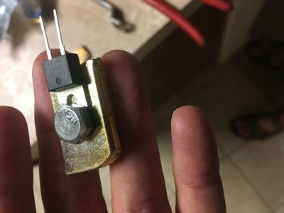
You want something that can handle more amps than you need for each individual circuit, with at least 45V or so blocking voltage and as low a passing resistance as possible (Schottky diode). The ones I used were 16A and 45V.
I bolted and glued mine to a homemade heat sink (bought some cheap steel cone nuts at the hardware store) but you could also use scrap aluminum or steel.
There’s a circuit diagram here that would be close to what you want, though you can delete diodes 1 and 2 since they’re not needed:
http://www.fordraptorforum.com/f265/help-spst-relay-connect-light-bar-high-beams-54732/index3.html#post1179657

I just wired mine up (using butt connectors crimped to the diode leads) into a big pigtail along with the relays and a fused lead and used bullet connectors so I could unplug and replace the whole thing if I ever have problems. When I wired the original lights I didn’t have all the materials (and time) to make the circuit, so I just included a spare connector on each of the individual switched circuits and proceeded with the installation and just used the individual switches for a few weeks. When I got around to building the harness all I had to do was tap into the high beam wire and plug in the harness to the spare connectors and connected it to the battery and it worked like a champ.
I’m sure there are fancier installations out there. I don’t have an electrical background beyond tinkering with my cars and boats so if someone with more automotive electrical or electronics expertise can chime in please do so.
If you PM me I’d be happy to share the hand sketched circuit I made or pics of the diodes I used and pigtail I built.


Forgot to mention...for the relays I bought two of these harnesses (link below) and cut them up to use what I needed. I cut off the switch on one and left the (blue) wire long to tap into the high beam wire as the trigger, using an aux switch (5) as the power feed to the relay (red wire that had a ring terminal) and connected the black ring terminal to ground (battery negative). The output (red wire that had a spade connector) was connected to the trigger (blue wire) on the second harness. The second harness was connected to the battery with red and black ring terminals and its output (red spade connector) fed my homemade diode pigtail which fed my three light circuits. (I removed the white and black switch wires on both harnesses and shortened wires as needed to make it all the right size)

https://www.amazon.com/gp/aw/d/B00R7IOOMS/ref=mp_s_a_1_1?ie=UTF8&qid=1512535358&sr=8-1-spons&pi=AC_SX236_SY340_QL65&keywords=led+light+wiring+harness&psc=1
 
Last edited:

KryptosXLayer2

Full Access Member
Joined
Aug 29, 2017
Posts
101
Reaction score
46
Location
Charlotte, NC, USA
Thanks @NDO, this is great information. If you have pictures on your phone, you can easily attach them to this thread in a new post by scrolling down to attachments, finding the pictures on your phone, and posting it. I am certainly more of a visual learner, so pictures are certainly going to be the best way for me to understand all that you did to get this going. I understand that not everyone takes pictures during the build, I sure didn't when I installed my LED amber and white warning lights, so no worries if they are not "in process" pictures but completed shots of the location of where you tapped.

I still have questions - probably more now that you posted this write up and the link to how you did yours. One thing I haven't seen anyone discuss was exactly where you got the tap for the high beams. Directly off the back of the headlight or through a fuse block? And then where did you mount your diode heat sink?

Based on the link you posted, you have an elaborate setup for using the switches, which I absolutely LOVE because you have qualifiers as to how you use them (do you need just one, three, TEN lights on at once? Use just one switch to select multiple!), but if I were going to do this for three individual switches, should I plan on doing this THREE times or is there a faster / easier / less material way of going about doing this?
 

NDO

Full Access Member
Joined
Feb 20, 2017
Posts
131
Reaction score
53
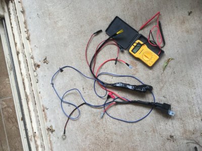
Thanks- didn’t realize it was that easy to attach. Not much to see, I can’t get more pics till Christmas but here’s a pic of a diode mounted to a heat sink and then a shot of the diode pigtail (on the right, with the black lead as the line side and the three individual red leads being the load side of the diodes.

To build the pigtail I took a short piece of 10-gauge wire with a connector on one end (matched to the un-pictured hot feed from the power relay) and spliced and soldered three short 12-ga or maybe it was 16-ga wires connected to the “input” side (anode) and three slightly longer red wires with bullet connectors connected to the “output” (cathode). I could have just as easily made the pigtail with two or four or five diodes and connectors depending how many individually switched circuits I wanted to feed. Think of it like a pipe header with individual hose taps each with a check valve to prevent backflow to the header.
Anyway, I taped up each diode individually then bundled them together. I used different length wires so they didn’t all bunch together (for better heat dispersion).

The left side of the pic is the “trigger” relay harness. The blue wire is what I spliced to the headlight. I just found the high beam hot wire on the left headlight, as suggested in another thread, and used a quick splice connector to tap it. That location seems to be an easy way to find and access the high beam wire as noted in the other thread. I routed the blue trigger wire from the relay location (next to the battery, just rearward of the windshield washer tank) around the top of the radiator and down to the headlight.


I mounted the pigtail (and the relays) just using wire ties.

My setup used switch 1 for the Onyx6, switch 3 for four of the cubes (two drivers on each side), switch 4 for two of the cubes (one flood on each side) and switch 5 for the combined circuit with all lights triggered by high beams. 80% of the time I use switch 5, but I sometimes use switch 4 (with headlights off) at boat ramps to avoid blinding other people launching boats, and I use switch 1 when I need light and my brights aren’t staying on due to ambient lighting or nearby signs/reflectors/etc.
(I have two rear cubes on switch 6, and kept switch 2 as a spare.)

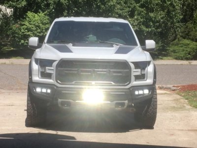
The last pic is with all the forward lights on.
 

Attachments

  • AD44ACD3-DC29-42A6-A629-E517A1463F1A.jpg
    AD44ACD3-DC29-42A6-A629-E517A1463F1A.jpg
    51.5 KB · Views: 50
  • 1CF0A2EE-A91F-4C90-9C5E-01479DFA2D44.jpg
    1CF0A2EE-A91F-4C90-9C5E-01479DFA2D44.jpg
    145.6 KB · Views: 51
  • 2884CDC3-CEB3-4CB8-9B1C-61A4167EA702.jpg
    2884CDC3-CEB3-4CB8-9B1C-61A4167EA702.jpg
    94.5 KB · Views: 63

Slow6

Full Access Member
Joined
Nov 13, 2017
Posts
476
Reaction score
198
Location
AK
Would be nice if there was an auxiliary box pre wired with a high beam, reverse light, door lock etc trigger wire. Ford missed on that one

Or if someone made a short adapter to put between factory harness and headlight that had a trigger wire (preferably high and low beam) so we wouldn’t have to splice into the factory wiring. If anyone comes up with the plug part numbers it’d be worth it to me to build one to avoid splicing the factory harness.
 

Hamm3r

Full Access Member
Joined
Dec 19, 2016
Posts
264
Reaction score
181
Location
N. GA
Since everyone here is apparently an electrical engineer and says "use diodes," can we get an idea as to WHAT diodes were used, please? I had to do a calculation the last time I used diodes to make my rear fog light switch work independent of a wired in second set of brake lights on a previous car, so when you all say "use diodes," can we get an idea as to what diodes were used?

I'm wiring up my OnX6 lights from @4x4TruckLEDs.com soon and would like some additional information. If relays are the way to go, please post a wiring diagram you used to prevent backfeed (I've seen one on another thread I believe). If you used diodes, please identify which one you used and where it was installed in the wiring.

This thread is USELESS with the posts saying to use this or that without saying HOW to use this or WHAT you actually used!
Well, here's a couple of options.

1. There's tons of good info in this thread already. If there's anything missing, be a big boy and figure it out on your own. There's good ole trial-and-error along with Google at your disposal.
2. Ask more detailed questions without accusing people of posting useless information simply because they didn't spoon-feed you every single detail and hold your hand throughout the entire process.
 

KryptosXLayer2

Full Access Member
Joined
Aug 29, 2017
Posts
101
Reaction score
46
Location
Charlotte, NC, USA
Well, here's a couple of options.

1. There's tons of good info in this thread already. If there's anything missing, be a big boy and figure it out on your own. There's good ole trial-and-error along with Google at your disposal.
2. Ask more detailed questions without accusing people of posting useless information simply because they didn't spoon-feed you every single detail and hold your hand throughout the entire process.

Exactly how NOT to be helpful on a forum, thanks for that stunning example! I'm sorry that I wasn't born with this knowledge, that Google didn't help me with the exact size of the diode for this application, where people had already done this had their setups mounted, but yet you felt the need to insult me because while I've been in this industry for nearly 20 years, I haven't worked on something like this before and I asked others who have been extremely helpful for their guidance.

Next time, move on and find some n00b to insult because I am not that guy.
 

Hamm3r

Full Access Member
Joined
Dec 19, 2016
Posts
264
Reaction score
181
Location
N. GA
Exactly how NOT to be helpful on a forum, thanks for that stunning example! I'm sorry that I wasn't born with this knowledge, that Google didn't help me with the exact size of the diode for this application, where people had already done this had their setups mounted, but yet you felt the need to insult me because while I've been in this industry for nearly 20 years, I haven't worked on something like this before and I asked others who have been extremely helpful for their guidance.

Next time, move on and find some n00b to insult because I am not that guy.

*shrug*
I can empathize with the fact that you wear your heart on your sleeve. However, I simply pointed out that you hopped in here accusing at least 4 people of being useless and not providing you with every last detail so you didn't have to think.

Instead, one way to attack this problem would have been to go out, wire some shit up, blow some relays, a fuse, or catch your truck on fire while screaming "oh shit, oh shit, oh shit." When you then had to turn around and fix your mistake, you damn well would have learned something, and wouldn't have had to go stamping your figurative feet on an internet forum because the coloring book wasn't already completed and posted in full 4k resolution for your consumption.

For example, I had never wired a single thing in my life before I got my Raptor. I'll bet I've blown a dozen fuses and popped a handful of relays. But, I learned. Sure, I had a ton of help from asking questions and doing research, but I never got frustrated and threw a temper tantrum because someone wasn't thorough enough.

Taking even just a simple step towards self sufficiency by fumbling around and solving a problem on your own is far more rewarding in its own right than flipping a switch and seeing your new, fancy lights working.

Cheers, friend! :patriot:
 

SpeedJunkie

Full Access Member
Joined
Sep 1, 2017
Posts
183
Reaction score
69
Does anyone know the color for the high beam wire on the 2018s?

Also, if I plan to have the high beam wire trigger a relay and the aux wire power the relay, is there any reason I need to use a diode? It seems not, but wanted to make sure.
 

K1llD4shN1n3

Full Access Member
Joined
Jul 27, 2016
Posts
546
Reaction score
331
Location
Colorado
Top