MagicMtnDan
FRF Addict
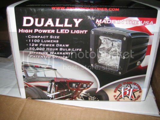
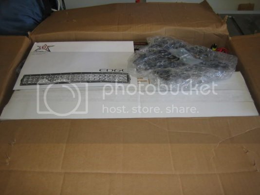
I've been jumping between threads to find the info I need so I thought I'd start a thread on installing Rigid Industries' 20" Lightbar and their Duallys.
I'll start by posting the installation instructions from Rigid and add my comments after and others can add theirs.
Here are the installation instructions provided by Taylor at Rigid Industries

Congratulations on your purchase from Rigid Industries.
Here are the instructions for installation of your new Rigid Lights on the
2010 Ford SVT Raptor
Rigid Industries lights:
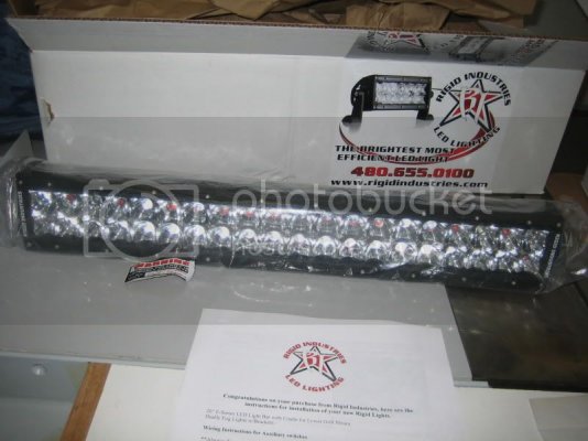
20” E-Series LED Light Bar with Cradle for Lower Grill Mount.
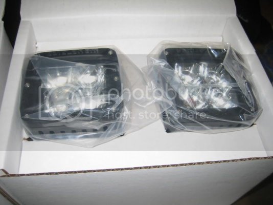
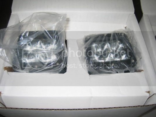
Dually Fog Lights w/Brackets.
Wiring Instructions for Auxiliary switches
**Always disconnect battery before servicing any fuses or electrical system**
Your Raptor is equipped with four factory “Upfitter” auxiliary switches. We need to get power to them. There are two locations that need to be addressed; inside the glove box and in the engine compartment under the hood. We will start with the glove box.
Open the glove box normally and empty out all contents. On the rear right and left sides there are tabs holding the box in place. Inside of the glove box: reach into the left and right inside of the box, pull in the sides where there is a tab holding it in place, the box should swing downward and towards the floor of the truck.
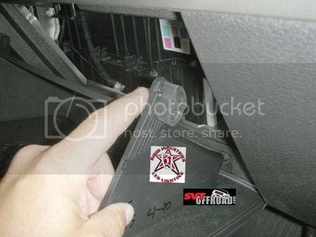
Glove box tab released.
Inside of the glove box area there is an access panel. Pull towards you to remove it and expose the wiring under the dashboard. After removing the access panel you will need to locate two bundles of 4 wires each. These wires are what you will need to mate to gain switch control to your lights.
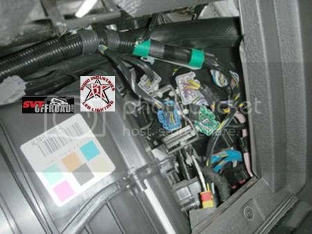
Wiring bundles after access panel is removed.
The switches will be wired as follows:
Aux switch 1 - 20” Lower grill LED Light (mate red to yellow)
Aux switch 2 - pair of inner fog lights (mate green to green w/black stripe)
Aux switch 3 - pair of outer fog lights (mate blue to purple)
If you would like switches set up differently, swap wiring where needed. Refer to your owners manual if you have any questions.
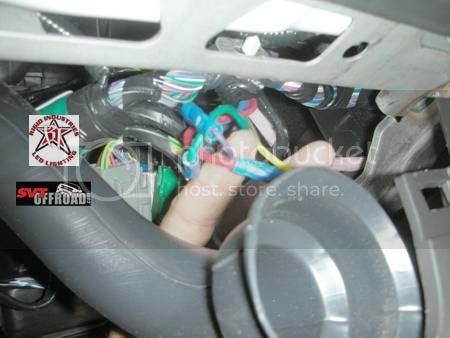
Mated wiring using butt connectors to show detail
Insert access panel and close glove box door while pulling in on the tabs.
Engine Compartment wiring
Open the hood of the truck and disconnect the battery. Locate the Power Distribution Box (page 365 in your owners manual). Open the box and you will notice the fuses are numbered.
Switch fuses are as follows: (page 326-329 in owners manual)
Switch# location Stock fuse Fuse needed for LED Light
1 18 30amp 10amp for 20” E-Series
2 19 30amp 5amp for pair of Dually’s
3 44 15amp 5amp for pair of Dually’s
4 28 10amp
Your lights will operate normally with the stock fuse configuration. We highly recommend changing to the proper fuse noted to protect your lights against potential damage from being over fused.
Locating the under-hood wiring for accessory hookup
It is on the passenger side of the truck above the wheel well. There are 4 wires, Blue, Red, Green, and Purple. Refer to your owners manual if you need help locating these.
Red wire is for the 20” Lower Grill LED (switch 1)
Green wire is for pair of inner Dually fog lights (switch 2)
Blue wire is for pair of outer Dually fog lights (switch 3)
These are the hot wires that will be connecting your lights to your switches.
The ground loops from your wiring harness and will be secured using the self drilling TEK screw installed next to the battery on the passenger side of inner fender. There are also stock bolts on the fender well that can be used if needed. Standard grounding principles apply.
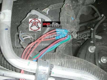
Wiring connected to light harness
Engine compartment wiring connected to light harness.
Installing lower grill 20” LED lights, or pairs of smaller lights.
The lower grill assembly is located under the license plate holes in the front bumper. There
are 5 hex screws. Use a 7/32 hex driver to remove these. Pull plastic grill forward to remove and expose inner bumper frame.
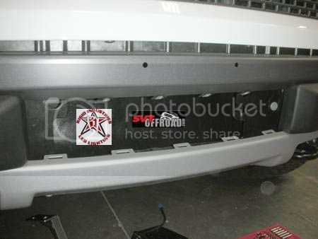
Lower grill removed.
Trimming your bumperettes (mini bumpers on either side of the lower grill)
We have found it easier to remove both bumperettes. Pull outward firmly for this stage. Just keep in mind that re-installing them can be tricky. There are four tabs on the backside of each bumerette, they are pliable. Bend the lower tabs outward and slide them under the base. Using a skinny screwdriver or small pick, pry the upper tabs out and into the slot on the top of the bumperette base. Modifying the bumperettes can be done without removing them. It just makes tightening the light into the cradle a little tricky.
To modify bumperettes drill ½” hole (per drawing) and cut out plastic to the edge.
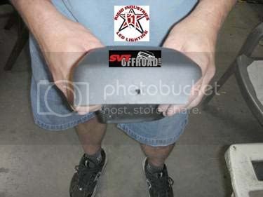
Above: Hole drilled
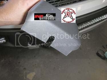
Above: Cutouts made
Installing the cradle for lower grill lights
Locate inner bumper frame, mark and drill two (1/2”) holes, one on each side per drawing.
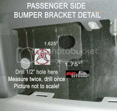
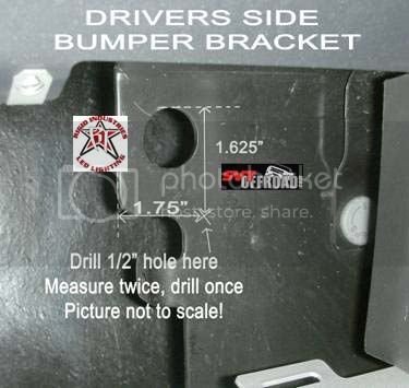
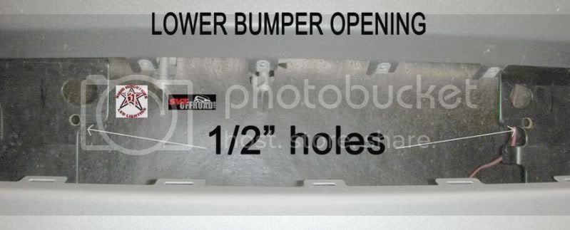
Lower Bumper Opening
Once you have the holes drilled for the cradle, insert the supplied carriage bolts into the slots on the light. Make sure slots for the light are facing up. Loosely bolt it into place using supplied washers and nylon lock nuts.
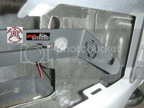
Bracket bolted in place loosely
Attaching the light to the cradle (make sure slots in bracket are facing up)
Rigid Industries E-Series lights are mounted using a black Delrin spacer/bushing and nylon lock nut on the end mount studs. The Delrin provides needed shock resistance, while the nut holds it in place.
Insert supplied Delrin bushing onto the end mount stud into endcap cavity of light. Then loosely spin on the nylon lock nut. Set the light into cradle and tighten until the light is snug in the cradle. Center light/cradle assembly in grill opening and tighten cradle nylon lock nuts on backside of bumper frame. Make your final adjustments, tighten end stud nylon lock nuts on light.
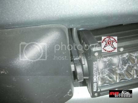
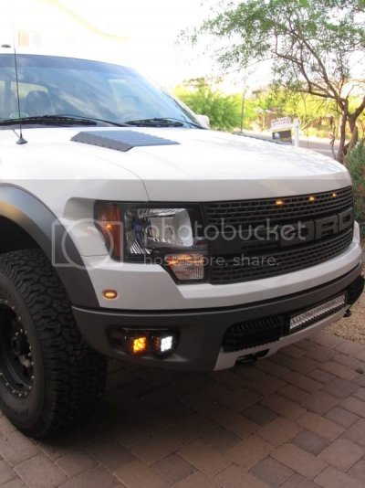
Above: Lightbar in place (left side)
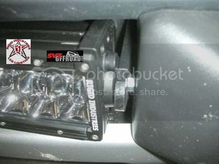
Above: Lightbar in place (right side)
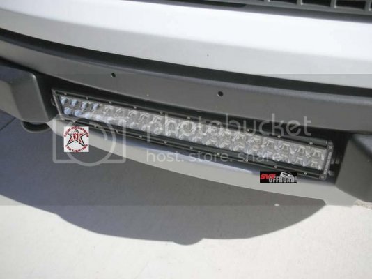
Above: Light and Bumperettes installed
Installing Fog Lights/Brackets
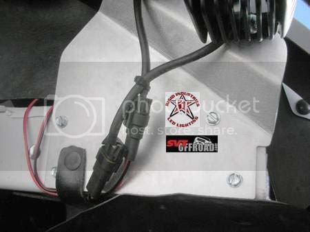
Locate the two aluminum fog light bracket plates.
Passenger Driver
The above picture shows non powder coated aluminum for detail of locating and drilling holes.
Laying under passenger side of fog light opening, locate painted steel support beam. It should be painted the same color as your truck.
Line up flat side of rear of bracket with backside of support beam and slide it inboard against the step down on the beam. The forward edge of the bracket, stepped down section with two holes, should be lining up with your fog light opening. Mark the 4 holes and drill using a 3/16” drill bit.
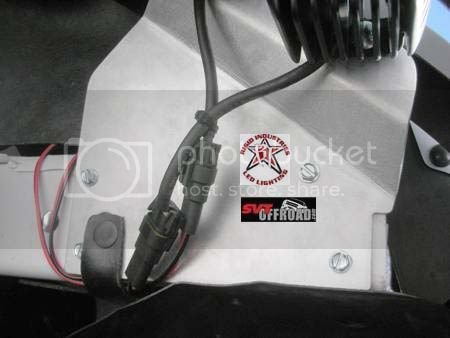
Above: Bracket in correct position (do not mount brackets yet)
Repeat for driver side. Remove black cap plug on beam, reinstall into larger hole in bracket, after bracket is in place. Do not mount brackets yet! Lights need to be installed onto them first.
Mounting Dually’s to bracket
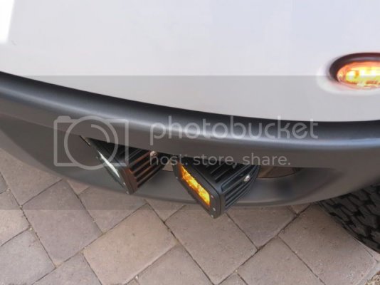
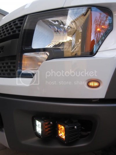
Notice how the brackets are mounted (stepped down section forward lining up with the fog opening). Mount Dually lights on the bottom of the plate as they are suspended from the bracket. Tighten cradle screws (on each side of light) then tighten main cradle stud onto the bracket with supplied hardware. Make sure the large flat washer is between the bracket and cradle of light. You will need to adjust these to line them up. Hold the bracket in place on the vehicle to get an idea of where you want them placed. Take the time here as it gets more difficult once mounted on the truck.
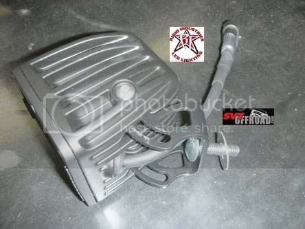
Above: Dually with washer (then mount to bracket)
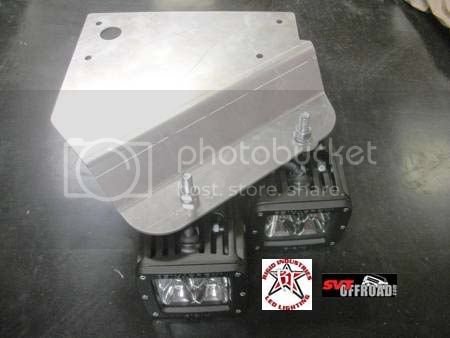
Above: Drivers Side with lights mounted.
Once adjusted hold bracket in place and install four supplied hex head screws per bracket with a 3/8” drive socket.
Installing the wiring harnesses
Lower Grill lights
With the truck prewired for accessories it is fairly simple to wire.
The 20” E-Series harness (hot wire is red) is soldered or, if you prefer, crimped with a butt connector to the red hot wire under the hood by the wheel well. The black wire is grounded with the supplied TEK screw, (included in kit) or grouped with the other grounds if installing fog light kit. Fish the plug end (male weatherpak connector) down behind the headlight bucket and over to the lower grill area. Plug into the light.
Fog Lights
Repeat above. For inner fog lights, connect the red wire to green wire on truck. For outer fog lights connect the red wire to blue wire on truck. Fish the male connectors down and over to connect to female connectors on fog lights.
Make sure all of your grounds are tied together and grounded. Check that all hardware is tight.
Thank you again for your purchase from Rigid Industries
PH 480-655-0100
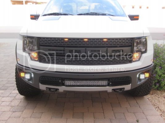
I'll start by posting the installation instructions from Rigid and add my comments after and others can add theirs.
Here are the installation instructions provided by Taylor at Rigid Industries

Congratulations on your purchase from Rigid Industries.
Here are the instructions for installation of your new Rigid Lights on the
2010 Ford SVT Raptor
Rigid Industries lights:
20” E-Series LED Light Bar with Cradle for Lower Grill Mount.
Dually Fog Lights w/Brackets.
Wiring Instructions for Auxiliary switches
**Always disconnect battery before servicing any fuses or electrical system**
Your Raptor is equipped with four factory “Upfitter” auxiliary switches. We need to get power to them. There are two locations that need to be addressed; inside the glove box and in the engine compartment under the hood. We will start with the glove box.
Open the glove box normally and empty out all contents. On the rear right and left sides there are tabs holding the box in place. Inside of the glove box: reach into the left and right inside of the box, pull in the sides where there is a tab holding it in place, the box should swing downward and towards the floor of the truck.

Glove box tab released.
Inside of the glove box area there is an access panel. Pull towards you to remove it and expose the wiring under the dashboard. After removing the access panel you will need to locate two bundles of 4 wires each. These wires are what you will need to mate to gain switch control to your lights.

Wiring bundles after access panel is removed.
The switches will be wired as follows:
Aux switch 1 - 20” Lower grill LED Light (mate red to yellow)
Aux switch 2 - pair of inner fog lights (mate green to green w/black stripe)
Aux switch 3 - pair of outer fog lights (mate blue to purple)
If you would like switches set up differently, swap wiring where needed. Refer to your owners manual if you have any questions.

Mated wiring using butt connectors to show detail
Insert access panel and close glove box door while pulling in on the tabs.
Engine Compartment wiring
Open the hood of the truck and disconnect the battery. Locate the Power Distribution Box (page 365 in your owners manual). Open the box and you will notice the fuses are numbered.
Switch fuses are as follows: (page 326-329 in owners manual)
Switch# location Stock fuse Fuse needed for LED Light
1 18 30amp 10amp for 20” E-Series
2 19 30amp 5amp for pair of Dually’s
3 44 15amp 5amp for pair of Dually’s
4 28 10amp
Your lights will operate normally with the stock fuse configuration. We highly recommend changing to the proper fuse noted to protect your lights against potential damage from being over fused.
Locating the under-hood wiring for accessory hookup
It is on the passenger side of the truck above the wheel well. There are 4 wires, Blue, Red, Green, and Purple. Refer to your owners manual if you need help locating these.
Red wire is for the 20” Lower Grill LED (switch 1)
Green wire is for pair of inner Dually fog lights (switch 2)
Blue wire is for pair of outer Dually fog lights (switch 3)
These are the hot wires that will be connecting your lights to your switches.
The ground loops from your wiring harness and will be secured using the self drilling TEK screw installed next to the battery on the passenger side of inner fender. There are also stock bolts on the fender well that can be used if needed. Standard grounding principles apply.

Wiring connected to light harness
Engine compartment wiring connected to light harness.
Installing lower grill 20” LED lights, or pairs of smaller lights.
The lower grill assembly is located under the license plate holes in the front bumper. There
are 5 hex screws. Use a 7/32 hex driver to remove these. Pull plastic grill forward to remove and expose inner bumper frame.

Lower grill removed.
Trimming your bumperettes (mini bumpers on either side of the lower grill)
We have found it easier to remove both bumperettes. Pull outward firmly for this stage. Just keep in mind that re-installing them can be tricky. There are four tabs on the backside of each bumerette, they are pliable. Bend the lower tabs outward and slide them under the base. Using a skinny screwdriver or small pick, pry the upper tabs out and into the slot on the top of the bumperette base. Modifying the bumperettes can be done without removing them. It just makes tightening the light into the cradle a little tricky.
To modify bumperettes drill ½” hole (per drawing) and cut out plastic to the edge.

Above: Hole drilled

Above: Cutouts made
Installing the cradle for lower grill lights
Locate inner bumper frame, mark and drill two (1/2”) holes, one on each side per drawing.


Lower Bumper Opening
Once you have the holes drilled for the cradle, insert the supplied carriage bolts into the slots on the light. Make sure slots for the light are facing up. Loosely bolt it into place using supplied washers and nylon lock nuts.

Bracket bolted in place loosely
Attaching the light to the cradle (make sure slots in bracket are facing up)
Rigid Industries E-Series lights are mounted using a black Delrin spacer/bushing and nylon lock nut on the end mount studs. The Delrin provides needed shock resistance, while the nut holds it in place.
Insert supplied Delrin bushing onto the end mount stud into endcap cavity of light. Then loosely spin on the nylon lock nut. Set the light into cradle and tighten until the light is snug in the cradle. Center light/cradle assembly in grill opening and tighten cradle nylon lock nuts on backside of bumper frame. Make your final adjustments, tighten end stud nylon lock nuts on light.

Above: Lightbar in place (left side)

Above: Lightbar in place (right side)

Above: Light and Bumperettes installed
Installing Fog Lights/Brackets
Locate the two aluminum fog light bracket plates.
Passenger Driver
The above picture shows non powder coated aluminum for detail of locating and drilling holes.
Laying under passenger side of fog light opening, locate painted steel support beam. It should be painted the same color as your truck.
Line up flat side of rear of bracket with backside of support beam and slide it inboard against the step down on the beam. The forward edge of the bracket, stepped down section with two holes, should be lining up with your fog light opening. Mark the 4 holes and drill using a 3/16” drill bit.

Above: Bracket in correct position (do not mount brackets yet)
Repeat for driver side. Remove black cap plug on beam, reinstall into larger hole in bracket, after bracket is in place. Do not mount brackets yet! Lights need to be installed onto them first.
Mounting Dually’s to bracket
Notice how the brackets are mounted (stepped down section forward lining up with the fog opening). Mount Dually lights on the bottom of the plate as they are suspended from the bracket. Tighten cradle screws (on each side of light) then tighten main cradle stud onto the bracket with supplied hardware. Make sure the large flat washer is between the bracket and cradle of light. You will need to adjust these to line them up. Hold the bracket in place on the vehicle to get an idea of where you want them placed. Take the time here as it gets more difficult once mounted on the truck.

Above: Dually with washer (then mount to bracket)

Above: Drivers Side with lights mounted.
Once adjusted hold bracket in place and install four supplied hex head screws per bracket with a 3/8” drive socket.
Installing the wiring harnesses
Lower Grill lights
With the truck prewired for accessories it is fairly simple to wire.
The 20” E-Series harness (hot wire is red) is soldered or, if you prefer, crimped with a butt connector to the red hot wire under the hood by the wheel well. The black wire is grounded with the supplied TEK screw, (included in kit) or grouped with the other grounds if installing fog light kit. Fish the plug end (male weatherpak connector) down behind the headlight bucket and over to the lower grill area. Plug into the light.
Fog Lights
Repeat above. For inner fog lights, connect the red wire to green wire on truck. For outer fog lights connect the red wire to blue wire on truck. Fish the male connectors down and over to connect to female connectors on fog lights.
Make sure all of your grounds are tied together and grounded. Check that all hardware is tight.
Thank you again for your purchase from Rigid Industries
PH 480-655-0100


