x-ray
Active Member
First off, a big thank you to @Nick@Apollo-Optics for getting me the Raptor 2017 30" S8 Grille LED Light Bar Kit for a great price. He also took great care of me when the kit arrived without the wiring harness. He made sure BD sent the harness out quick and answered my call for tech support super quick when I was having trouble with the less than complete/clear instructions.
I did finally get the light installed but it took me nearly 4 hours. With more detailed instructions I could have done it in under 2.
I actually had a hard time getting the light aimed perfectly straight and had to remove and reinstall the light not once, but twice after the original install and did the final removal and reinstall in under 45 minutes.
I figured I would try and make things more clear and help others out who might not be as mechanically savvy like me.
The kit itself is great. The light is built like a tank. Very high quality. The brackets are thick and strong and either painted or powder coated black. Nice hardware. The wiring harness is great and makes the kit pretty much plug and play. I do with they would have had a slice connector installed on the green power wire for the amber lights but otherwise it makes the install very easy.
My install suggestions/directions:
First off, a list of tools would be great! Any instructions should include this at the top so you know what to have on hand before you start...not included in the BD instructions...
Instructions for reference:
Link
Tools needed:
1. A trim tool removal kit. Something like: This from Amazon.
2. 8mm, 10mm and 11mm sockets
3. Cordless drill or socket driver with a short extension to get the two 8 mm bolts holding the grill to the truck and the single bolt in the middle of the inner and outer grills together.
4. Towel, blanket or carpet to lay grill on.
5. If you will be connecting the amber markers in the light to an upfitter switch (I did #5) you need a butt connector and maybe some electrical tape.
These are the install instructions from BD with my additions.
1. Remove plastic push pins (12 in total) located in the circled positions shown below.
My input: Use one of the trim removal tools or the plastic push pin tool to separate the head of the pushpin and raise it up, then get under the rest of the pushpin and pry it out.
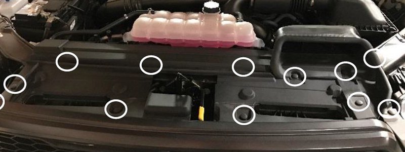
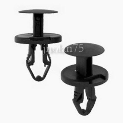
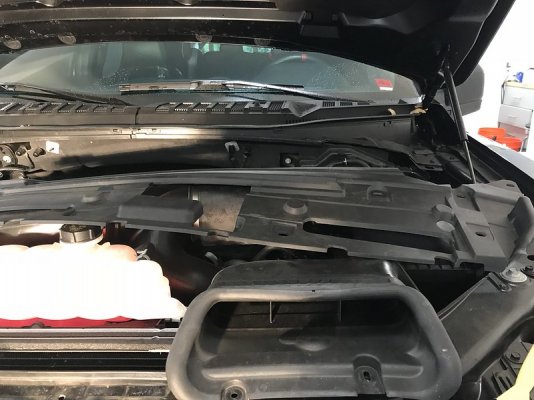
Once all 12 are removed, you can remove the plastic shroud covering the top of the grill and set it back on the engine.
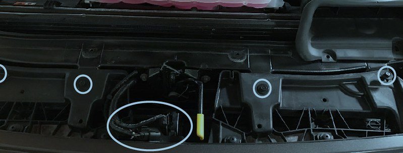
2. Disconnect the two wiring connectors, and the quick-disconnect for the fluid washer fluid hose. Then remove the four bolts securing the front grille, shown below.
Remove the wiring connectors by pushing the release lever and sliding out.
You can use a small pry tool to remove the washer fluid tube
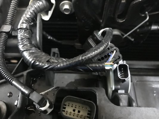
3. Gently pull on the painted facia piece around headlight starting with the upper most section, closest to the push pin that was removed in the previous step. You will hear a distinct “pop” when the shroud is disconnected.
This is a really good description. Wear gloves, gentle tug and you will feel each piece pop loose.Start at the top, move down and then laterally. You need to rotate the piece out from under the headlight pulling more medially by the grill than laterally by the head light. Lay each painted trim piece some place safe, out of the way so you don't step on them...
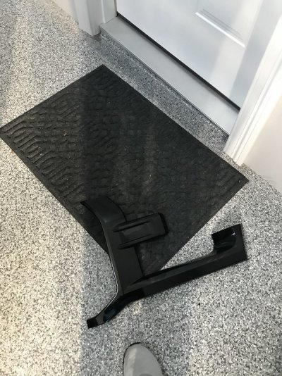
4. Remove the three push pins on each side of the grille, which attach the flexible rubber guards.
These push pins are different than the ones you removed in step 1. These you essentially just get under and pry them out.
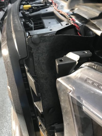
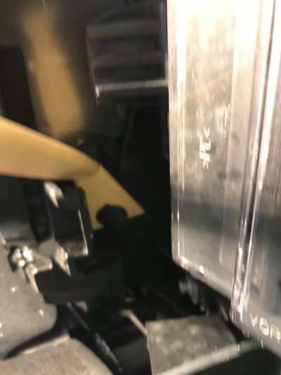
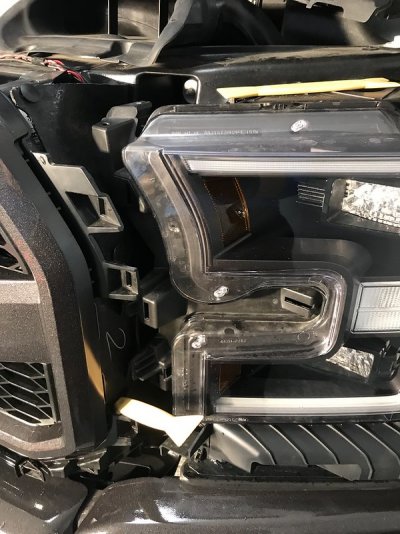
5. Remove the 8mm grille support bolt located behind the painted headlight facia on the lower left and right hand sides.
You need a short extension to reach these bolts.
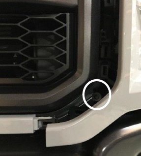
NOTE: Before you remove the grille from your vehicle, you may want to lay something down on your work space that won’t scratch the grille. Blanket,
towel, carpet etc.
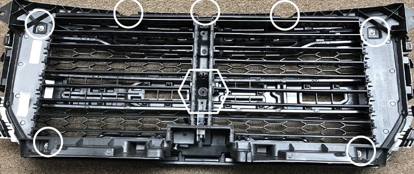
6. Gently lift grille up, one to two inches, and pull away from the vehicle to free it. Lay grille facedown and remove the seven nuts and one bolt outlined below. Then remove the four push pins on top of
the grille.
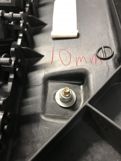
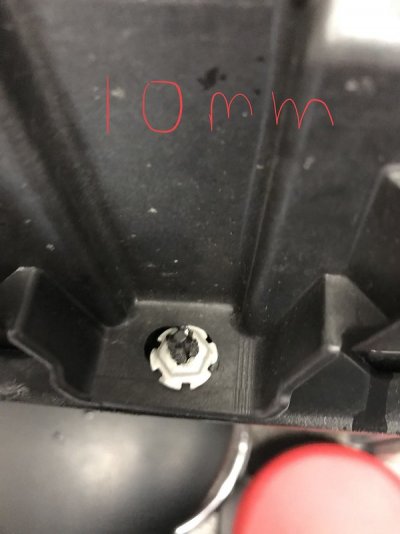
The 7 nuts described are 4 nuts at each corner and 3 odd looking silver nuts over plastic screw-like thingys at the bottom of the grill. All are 10mm in size.
I tried to remove the 4 nuts at the corners but they never wanted to come off.
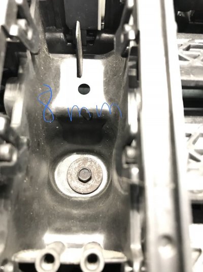
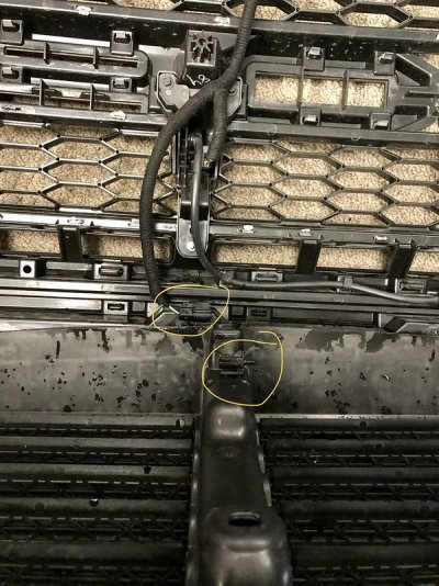
They just spin. This is actually removing them from the plastic fastener underneath so just unscrew for awhile and then move on. I had a hard time with the smaller flimsy nuts at the bottom of the grill. I basically put the socket on and then pried from underneath with one of the plastic pry tools. If anyone has any insight, I would love it because it sort of strips the plastic threads with my move. The push pins on the top look different than in step one but are removed in a similar manner. The center bolt is 8mm and needs a short extension. As you separate the grill you need to unhook the wiring harness at the top of the grill and the washer fluid tube. There is also a wiring harness at the bottom of the grill between the two pieces which needs to be unhooked once the grill is apart.
7. Separate the two sections of the grille and lay the inner-grille down, with the front facing upward.
Loosely install the left and right brackets then the light. With all brackets assembled tighten bolts.
This bolded line gave me the most problems. No real explanation on "how"
to install the brackets and the picture provided was of little help.
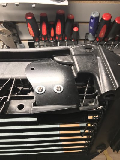
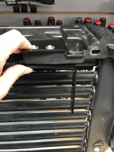
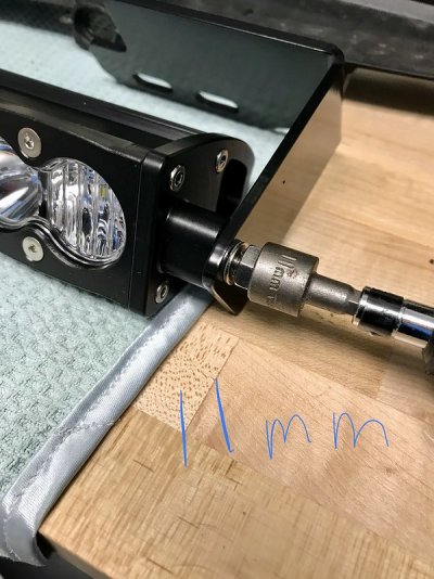
The bracket has two pieces for each side. It works like a sandwich. The flat/rectangular piece goes on top and the L bracket goes under the grill. You put 3 screws through the top bracket with washers under each head and then thread the screws through the bottom bracket, place another washer over the screw and then a nut. You use an allen wrench on top and a small 10 mm wrench on the bolt to tighten things up.
When you install the light, the best way to get it straight and aimed correctly I found out the hard way it is not an easy task as it is really hard to judge and as you tighten the nylock nuts (11mm) it changes the angle of the light. The third time I tried to adjust the light I figured out that the best way is to take the inner grill back to the truck with the light installed and place it back where it goes. Line up all the bolt holes so they align. Then, grab a small level and use it on the face of the light and get it level or minimally angled up. Tighten the nylock nuts carefully checking level as you tighten. Once it is tightened, take the inner grill back off and over to the outer grill and begin reassembly.
From here down, I haven't added anything as I am too tired and I had less trouble with the rest.
8. Pull the wiring to the front of the grille and use the hole in the bracket to zip tie the cord away from the louvres. Route the wire through the upper left hand corner of grille where there is already a slot cut out, as shown in the photo below.
9. If all four of the gold studs remained in the front section of the grille when you removed the nuts in step 6 (resembling Figure 2), proceed to step 11.
10. If any of the gold studs remained in the rear section of the grille as you loosened the nuts in step 6 (resembling Figure 1) you will need to remove the nuts, and reinstall the studs into the front section of the grille. Once complete, all four corners of the front grille section will resemble Figure 2.
NOTE: Removal of the studs can be completed by holding the flat or built-in washer portion of the stud with Channellock pliers, while backing the nut off with a 10mm socket or wrench. Make sure not to damage the threads on the studs.
11. With the light bar aimed straight ahead, lay the front section of the grille onto the rear section so you can make adjustments and route the wiring up and out of the grille assembly.
12. Once the light is angled in the desired direction, and wiring is secure, tighten the nyloc nuts on the outside of the brackets to lock in the orientation of the light.
13. Cut the factory zip tie that contains the push pin. Remove the old zip tie and insert the provided zip tie into the plastic fastening device. Pull wiring taut around the center mount, and tighten the zip tie to secure wiring in place.
NOTE: Make sure wiring is routed down the correct side, as shown in the picture above.
Figure 1
Figure 2
14. With the wiring secure, install and tighten down the seven nuts and one center bolt that were removed in step 6.
15. Install the grille assembly back onto vehicle and reattach all wiring, tubing, screws, and push pins from the disassembly process.
Wiring:
1. Refer to the owner’s manual for a 15amp auxiliary switch, and the appropriate wiring colors - (AUX 1 green/blue or AUX 2 gray/yellow).
NOTE: If you are also running the Baja Designs Fog Pocket Kit, you will need to utilize a 10amp or 5 amp switch for the S2 fog lights, leaving AUX 1 or AUX 2 free for the installation of the 30” S8.
2. Once you have determined the appropriate wire color, attach the white wire of the supplied up-fitter harness to your wire of choice by using the included splice connector. Then attach the black wire of the up-fitter harness to the battery/chassis ground.
3. The amber backlit function of the S8 is powered through the green wire in the harness. Depending on your preference, you can power this function one of two ways. The first being to tie into the trucks existing amber-light wiring.
4. The second option is to connect the green wire to one of the auxiliary switch wires, in the same fashion you did in steps 1 and 2. Any available AUX switch will work, but AUX 5 or AUX 6 (each rated at 5amps) is more than sufficient for the amber backlighting
I did finally get the light installed but it took me nearly 4 hours. With more detailed instructions I could have done it in under 2.
I actually had a hard time getting the light aimed perfectly straight and had to remove and reinstall the light not once, but twice after the original install and did the final removal and reinstall in under 45 minutes.
I figured I would try and make things more clear and help others out who might not be as mechanically savvy like me.
The kit itself is great. The light is built like a tank. Very high quality. The brackets are thick and strong and either painted or powder coated black. Nice hardware. The wiring harness is great and makes the kit pretty much plug and play. I do with they would have had a slice connector installed on the green power wire for the amber lights but otherwise it makes the install very easy.
My install suggestions/directions:
First off, a list of tools would be great! Any instructions should include this at the top so you know what to have on hand before you start...not included in the BD instructions...
Instructions for reference:
Link
Tools needed:
1. A trim tool removal kit. Something like: This from Amazon.
2. 8mm, 10mm and 11mm sockets
3. Cordless drill or socket driver with a short extension to get the two 8 mm bolts holding the grill to the truck and the single bolt in the middle of the inner and outer grills together.
4. Towel, blanket or carpet to lay grill on.
5. If you will be connecting the amber markers in the light to an upfitter switch (I did #5) you need a butt connector and maybe some electrical tape.
These are the install instructions from BD with my additions.
1. Remove plastic push pins (12 in total) located in the circled positions shown below.
My input: Use one of the trim removal tools or the plastic push pin tool to separate the head of the pushpin and raise it up, then get under the rest of the pushpin and pry it out.


Once all 12 are removed, you can remove the plastic shroud covering the top of the grill and set it back on the engine.

2. Disconnect the two wiring connectors, and the quick-disconnect for the fluid washer fluid hose. Then remove the four bolts securing the front grille, shown below.
Remove the wiring connectors by pushing the release lever and sliding out.
You can use a small pry tool to remove the washer fluid tube


3. Gently pull on the painted facia piece around headlight starting with the upper most section, closest to the push pin that was removed in the previous step. You will hear a distinct “pop” when the shroud is disconnected.
This is a really good description. Wear gloves, gentle tug and you will feel each piece pop loose.Start at the top, move down and then laterally. You need to rotate the piece out from under the headlight pulling more medially by the grill than laterally by the head light. Lay each painted trim piece some place safe, out of the way so you don't step on them...

4. Remove the three push pins on each side of the grille, which attach the flexible rubber guards.
These push pins are different than the ones you removed in step 1. These you essentially just get under and pry them out.


5. Remove the 8mm grille support bolt located behind the painted headlight facia on the lower left and right hand sides.
You need a short extension to reach these bolts.

NOTE: Before you remove the grille from your vehicle, you may want to lay something down on your work space that won’t scratch the grille. Blanket,
towel, carpet etc.
6. Gently lift grille up, one to two inches, and pull away from the vehicle to free it. Lay grille facedown and remove the seven nuts and one bolt outlined below. Then remove the four push pins on top of
the grille.
The 7 nuts described are 4 nuts at each corner and 3 odd looking silver nuts over plastic screw-like thingys at the bottom of the grill. All are 10mm in size.
I tried to remove the 4 nuts at the corners but they never wanted to come off.
They just spin. This is actually removing them from the plastic fastener underneath so just unscrew for awhile and then move on. I had a hard time with the smaller flimsy nuts at the bottom of the grill. I basically put the socket on and then pried from underneath with one of the plastic pry tools. If anyone has any insight, I would love it because it sort of strips the plastic threads with my move. The push pins on the top look different than in step one but are removed in a similar manner. The center bolt is 8mm and needs a short extension. As you separate the grill you need to unhook the wiring harness at the top of the grill and the washer fluid tube. There is also a wiring harness at the bottom of the grill between the two pieces which needs to be unhooked once the grill is apart.


7. Separate the two sections of the grille and lay the inner-grille down, with the front facing upward.
Loosely install the left and right brackets then the light. With all brackets assembled tighten bolts.
This bolded line gave me the most problems. No real explanation on "how"
to install the brackets and the picture provided was of little help.
The bracket has two pieces for each side. It works like a sandwich. The flat/rectangular piece goes on top and the L bracket goes under the grill. You put 3 screws through the top bracket with washers under each head and then thread the screws through the bottom bracket, place another washer over the screw and then a nut. You use an allen wrench on top and a small 10 mm wrench on the bolt to tighten things up.
When you install the light, the best way to get it straight and aimed correctly I found out the hard way it is not an easy task as it is really hard to judge and as you tighten the nylock nuts (11mm) it changes the angle of the light. The third time I tried to adjust the light I figured out that the best way is to take the inner grill back to the truck with the light installed and place it back where it goes. Line up all the bolt holes so they align. Then, grab a small level and use it on the face of the light and get it level or minimally angled up. Tighten the nylock nuts carefully checking level as you tighten. Once it is tightened, take the inner grill back off and over to the outer grill and begin reassembly.


From here down, I haven't added anything as I am too tired and I had less trouble with the rest.
8. Pull the wiring to the front of the grille and use the hole in the bracket to zip tie the cord away from the louvres. Route the wire through the upper left hand corner of grille where there is already a slot cut out, as shown in the photo below.
9. If all four of the gold studs remained in the front section of the grille when you removed the nuts in step 6 (resembling Figure 2), proceed to step 11.
10. If any of the gold studs remained in the rear section of the grille as you loosened the nuts in step 6 (resembling Figure 1) you will need to remove the nuts, and reinstall the studs into the front section of the grille. Once complete, all four corners of the front grille section will resemble Figure 2.
NOTE: Removal of the studs can be completed by holding the flat or built-in washer portion of the stud with Channellock pliers, while backing the nut off with a 10mm socket or wrench. Make sure not to damage the threads on the studs.
11. With the light bar aimed straight ahead, lay the front section of the grille onto the rear section so you can make adjustments and route the wiring up and out of the grille assembly.
12. Once the light is angled in the desired direction, and wiring is secure, tighten the nyloc nuts on the outside of the brackets to lock in the orientation of the light.
13. Cut the factory zip tie that contains the push pin. Remove the old zip tie and insert the provided zip tie into the plastic fastening device. Pull wiring taut around the center mount, and tighten the zip tie to secure wiring in place.
NOTE: Make sure wiring is routed down the correct side, as shown in the picture above.
Figure 1
Figure 2
14. With the wiring secure, install and tighten down the seven nuts and one center bolt that were removed in step 6.
15. Install the grille assembly back onto vehicle and reattach all wiring, tubing, screws, and push pins from the disassembly process.
Wiring:
1. Refer to the owner’s manual for a 15amp auxiliary switch, and the appropriate wiring colors - (AUX 1 green/blue or AUX 2 gray/yellow).
NOTE: If you are also running the Baja Designs Fog Pocket Kit, you will need to utilize a 10amp or 5 amp switch for the S2 fog lights, leaving AUX 1 or AUX 2 free for the installation of the 30” S8.
2. Once you have determined the appropriate wire color, attach the white wire of the supplied up-fitter harness to your wire of choice by using the included splice connector. Then attach the black wire of the up-fitter harness to the battery/chassis ground.
3. The amber backlit function of the S8 is powered through the green wire in the harness. Depending on your preference, you can power this function one of two ways. The first being to tie into the trucks existing amber-light wiring.
4. The second option is to connect the green wire to one of the auxiliary switch wires, in the same fashion you did in steps 1 and 2. Any available AUX switch will work, but AUX 5 or AUX 6 (each rated at 5amps) is more than sufficient for the amber backlighting

