Aftermarket gauge question, aeroforce interceptor

Disclaimer: Links on this page pointing to Amazon, eBay and other sites may include affiliate code. If you click them and make a purchase, we may earn a small commission.

bsimms89

Active Member
Joined
Apr 27, 2014
Posts
71
Reaction score
21
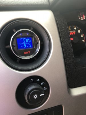
I'm getting ready to install a whipple kit in my 2014 raptor and want to install a couple gauges to keep an eye on things like AFR, intake air temps, and boost. I am currently leaning toward 2 aeroforce interceptor gauges in vent pods on either side of the steering wheel. I know the aeroforce interceptor gets its information through the OBD2 jack. I just was curious if the raptor registers the new information from the whipple such as boost level and intake air temp after the intercooler such that the gauges would get that information from the OBD 2.
 
OP
OP
bsimms89

bsimms89

Active Member
Joined
Apr 27, 2014
Posts
71
Reaction score
21
The truck does monitor intake temp after the intercooler (iat2) and can be seen on the aero force interceptors with just the obd-II hookup, you wire in a new pin to a blank slot in the pcm plug when you install the whipple. The truck doesn’t monitor boost/vacuum pressure, i installed a pressure sensor hooked up to a barb into the manifold, I then had to run a wire from the sensor into the cab and into the back of the gauge as an analog input, I got the 12v sensor from aero force and they’re instructions are straight forwards
 

KYmxracer52

Full Access Member
Joined
Nov 1, 2013
Posts
174
Reaction score
53
Location
Central KY
The truck does monitor intake temp after the intercooler (iat2) and can be seen on the aero force interceptors with just the obd-II hookup, you wire in a new pin to a blank slot in the pcm plug when you install the whipple. The truck doesn’t monitor boost/vacuum pressure, i installed a pressure sensor hooked up to a barb into the manifold, I then had to run a wire from the sensor into the cab and into the back of the gauge as an analog input, I got the 12v sensor from aero force and they’re instructions are straight forwards


Do you have a pic of your manifold where you tapped into for boost/vacuum? I bought the boost sensor from Aeroforce and plan to install it all this week. Did you mount that sensor in the engine bay or run it into the cab?
 

sln157

Member
Joined
Dec 23, 2016
Posts
10
Reaction score
4
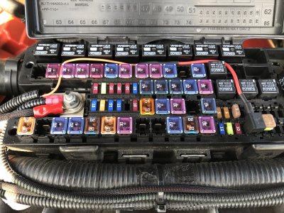
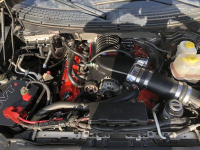
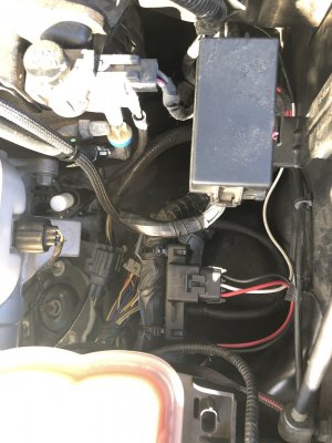
B2B56A54-C18F-42E3-A8DA-9110E842790E.jpeg A15B927E-D4E9-4136-B340-8E5672C81A01.jpeg BC1B1E53-CABE-4D12-B7C1-0346E33B136E.jpeg D1398C7B-CF18-403B-97C3-5A791B63EDCF.jpeg 0E08A9CA-D1AF-41A6-9085-95993CCC1F24.jpeg Installed mine last year and it was pretty straight forward. Used the 2bar GM Map Sensor, 5v Regulated Power Supply, and Add-A-Circuit. You can see the add-a-circuit in the fuse panel photo and main power (braided sleeve) connected to the power block. Used a factory ground just under the air filter (same place I grounded the heat exchanger fans). Mounted the Map sensor to a wire harness on the drivers side near firewall and one of the threaded NPT ports on the Whipple Intake manifold (pictured). Used Analog 1 port and set it to 5.8 for slope and -13.2 for intercept. I’m near sea level but still had to adjust my intercept and ended at -13.0 to read 0 with ignition on. Instructions are all pretty straight forward, I stick with coolant temp and vacuum/boost monitoring for mine. Hope this helps!
 
OP
OP
bsimms89

bsimms89

Active Member
Joined
Apr 27, 2014
Posts
71
Reaction score
21
I’ll get picks tomorrow morning, I installed the barb fitting in the same place he did in the manifold, but I used a 12v pressure sensor, I mounted it up under the plastic at the top of the firewall behind the hood, I ran the ground to the one at the passenger top firewall ( I would’ve used the ground under the air filter that was used for the intercooler pump but I had already put the air filter assembly together and didn’t want to take the whole box back out to get to it), and the power wire I spliced into the wire for the intercooler pump since the pressure sensor has almost no draw and they are both key switched 12v power, then the analog wire for the gauge I ran in through the driver side grommet and up into my a pillar mounted gauge
 

KYmxracer52

Full Access Member
Joined
Nov 1, 2013
Posts
174
Reaction score
53
Location
Central KY
View attachment 124130 View attachment 124131 View attachment 124132 View attachment 124134 View attachment 124135 Installed mine last year and it was pretty straight forward. Used the 2bar GM Map Sensor, 5v Regulated Power Supply, and Add-A-Circuit. You can see the add-a-circuit in the fuse panel photo and main power (braided sleeve) connected to the power block. Used a factory ground just under the air filter (same place I grounded the heat exchanger fans). Mounted the Map sensor to a wire harness on the drivers side near firewall and one of the threaded NPT ports on the Whipple Intake manifold (pictured). Used Analog 1 port and set it to 5.8 for slope and -13.2 for intercept. I’m near sea level but still had to adjust my intercept and ended at -13.0 to read 0 with ignition on. Instructions are all pretty straight forward, I stick with coolant temp and vacuum/boost monitoring for mine. Hope this helps!

Where is your 5v add a circuit used? The one pictured looks like the Whipple one I have for the pump. Do you remember what size nipple you used in the manifold, like thread and diameter?
 

KYmxracer52

Full Access Member
Joined
Nov 1, 2013
Posts
174
Reaction score
53
Location
Central KY
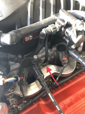
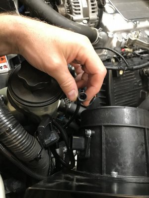
Since both of you guys have the Whipple setup, did either of your kits have this connection? It’s part of the h/e pump relay that is shown to be mounted near the radiator fill neck. It’s an orange single wire. Have no idea what it goes to and the instructions make no mention of it.

331E9D0F-4944-4BAD-B855-CA85F095E4E5.jpeg

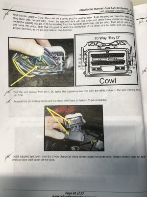
Step #114 in the manual states to splice the wire into the wire from pin 56. I stripped back some sheathing and soldered it to the oem wire. Is that what they wanted done? I received a butt connector in a hardware bag but have no idea what it’s for unless it was that step. I thought maybe they wanted you to cut the oem wire and re-connect them all together using the butt connector. What did you guys during that step?
AA131248-5386-4B00-BD16-72B88524BD26.jpeg
 

sln157

Member
Joined
Dec 23, 2016
Posts
10
Reaction score
4
Let me pull it up and give it a look to make sure I’m not crazy, it was last May since I did my install. I’ll get back with you.

Edit: I stand corrected, you were right on the orange wire & add-a-circuit in the photo (was for the pump). Forgot I’d ordered the add-a-circuit but didn’t need it since I used the 5v adapter. I’ve since remounted the map sensor and sheathed the wire loom at the firewall closer to the grommet where the wires ran through for the gauge. I’d of rather tapped into a source like bsimms89 as I’ve already had one 5v regulator go bad. As for the vacuum/boost port, it’s a 1/8” NPT I ordered from summit with neoprene tubing. I did use the butt connector provided to tap in as well. Some of the instructions were somewhat vague and when I ordered my kit last March I was one of the few to get the Gen3 at the time. By the time I received mine in May and installed it, I’d had it on for less than a week and it seized (rotors shredded), it was replaced free of charge due to a freak assembly issue before it was shipped I was told. I’d already installed billet OPG’s prior to the blower but had a panic attack I’d lost oil pressure as the belt was tight enough when it seized that the motor wouldn’t crank. After the replacement unit and JDM tune it’s been all smiles and no issues for a year now. Mike Malicoat from Whipple was a huge help during the install process with answering my questions. I ordered the stage2 kit and along with new and updated parts, the manual supplied was outdated.
 
Last edited:
Top