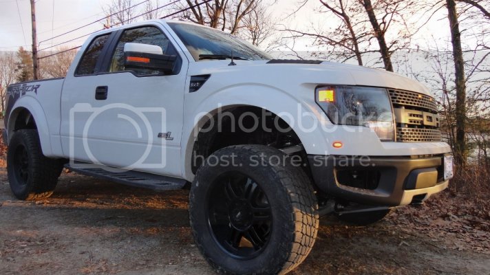
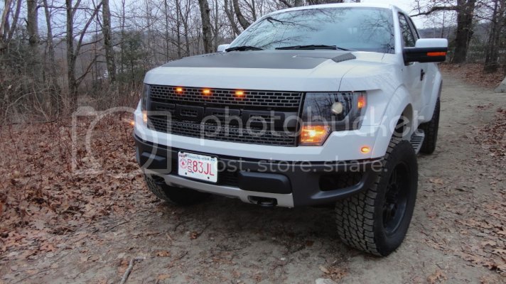
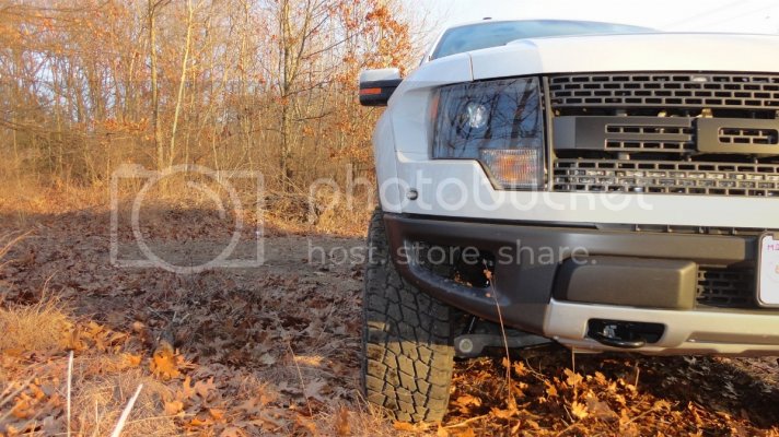
First of all, get the truck in the air and remove the tire. If you're using a floor jack be sure to set the e-brake, chock the wheels and USE JACK STANDS. You're going to be getting very intimate with your front suspension which requires a lot of time under the truck.
Safety first. Refer to manufacturer for torque specs. Be sure to check all bolts after 100 miles. This is intended to be a helpful guide to supplement an intermediate automotive knowledge and good automotive repair practices.
- Difficulty:
1 2 3 4 5 6 7 8 9 10
- Time depending on automotive repair skills, availability to a floor lift and air tools:
4-10 hours
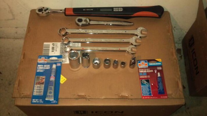
- Tools Needed:
15mm deep socket or ratchet wrench (stock top shock mount bolts)
18mm socket (sway bar link)
18mm wrench (sway bar link)
21mm socket (upper control arm mounts)
21mm wrench (tie rod, upper control arm)
27mm wrench (or 1 1/16) (stock lower shock mount bolt)
30mm socket (stock lower shock mount nut)
9/16" socket (ICON upper shock mount bolts)
10mm socket (ground point bolt on passenger side)
5/16" nut driver (ICON remote reservoir hose clamps
15/16" wrench (ICON lower shock mount bolt)
15/16" socket (ICON lower shock mount nut)
12pt 1/2" socket (ICON uniball adapter pin)
12pt 3/8" socket (1/4" drive) (ICON UCA pinch joint bolts)
Razor Blades (for cutting assorted zip ties and tape)
Vice Grips
Channel Locks or Pliers
Breaker Bar (stock lower shock bolt is torqued to >400 ft-lbs from factory)
Ball Peen Hammer
6" 1/2" drive socket extension
Torque Wrench
Drill (or grinder - for fitting clearance)
Grinding stones
Anti-Seize
Metric and Standard Alan wrench sets
Blue "removable" Loctite
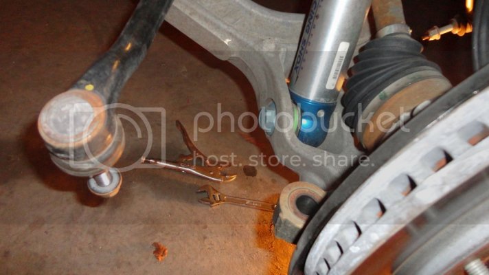
1. Remove the tie rod end from the spindle using a 21mm wrench.
*Tip: Leave the nut threaded 1 or 2 turns and use a ball peen hammer or mini-sledge to firmly strike the bottom of the stud to release the taper from the spindle.
*Tip: If the stud starts to spin when you're removing the nut you can use vice-grips to grab the bottom of the stud while turning the nut.
2. Remove the UCA pin from the spindle using a 21mm wrench. Use the same method and tips as with the tie rod stud.
The hub assembly will now be loose. Remove the zip tie and clips securing the lines to the upper control arm and bracket.
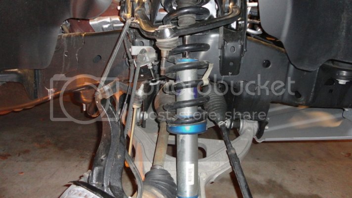
3. Remove the top factory shock mount nuts using a 15mm deep well socket or ratcheting wrench. Do not reuse the coilover hat when installing the ICON 3.0 coilovers.
-Release any wiring conduit from its clips and route it out of the way for now.
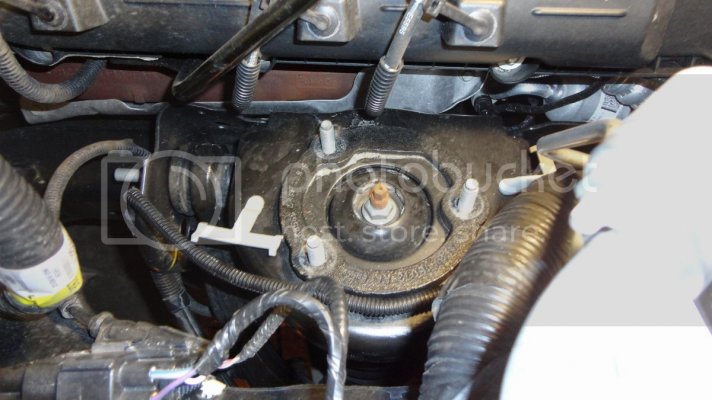
4. Remove the lower shock mount bolt(the big blue one) using a 27mm wrench on the bolt and a 30mm socket with 6" extension on the nut.
*Tip: A powerful impact gun is recommended. If removing by hand, you will want to use a long breaker bar to gain leverage. This bolt is torqued to 420 lb-ft from the factory.
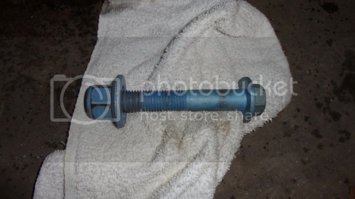
5. Remove the sway bar link from the lower control arm using an 18mm wrench. The suspension will now be at full droop and will make removing the shock much easier.
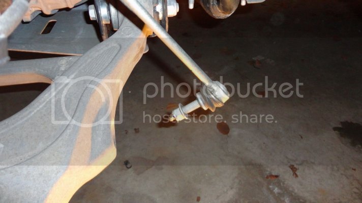
6. Remove the shock from the truck by lifting up and pulling the bottom out to clear the lower control arm.
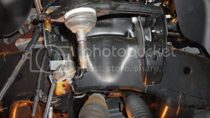
7. Remove the factory UCA from the frame by removing the 2 bolts using a 21mm wrench(nut) and 21mm socket(bolt).
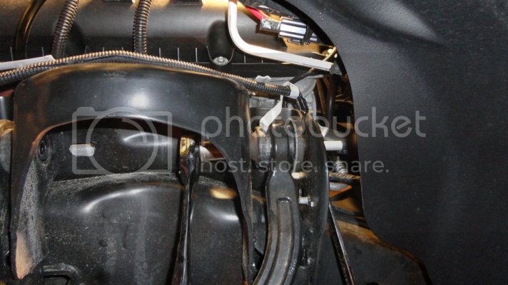
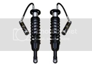
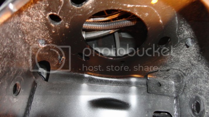
8. Prepare the spring bucket for installation of the ICON 3.0 coilover. The ICON shock uses a remote reservoir and has a hose fitting on the inboard side of the shock which passes through the center hole of the spring bucket.
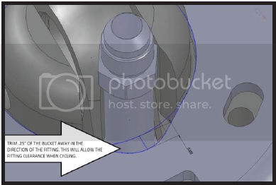
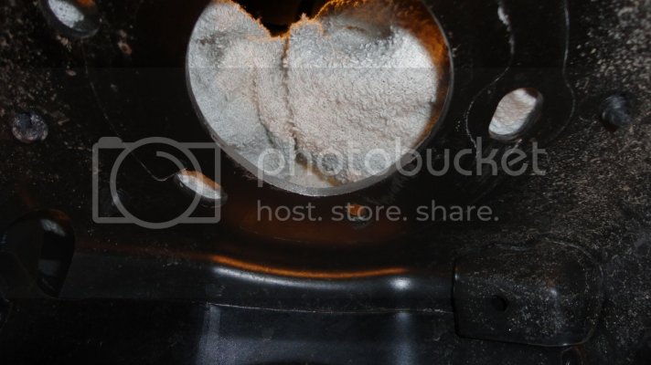
You will need to grind out approximately 1/4" of material from the inside quarter of the hole in the spring bucket. This is to add clearance for the hose fitting.
*The fitting will clear the spring bucket without grinding, but the clearance will be necessary for when the suspension is under full compression.
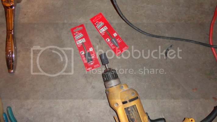
Using a grinding stone (attached to a drill or die grinder), gradually remove material leaving no sharp edges. When finished it's recommended you coat any exposed metal with black Rust-o-Leum spray paint or a similar product.
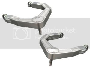
9. While your spray paint is drying, prepare the ICON Billet Aluminum Uniball Upper Control Arm for installation:
- Loosen the pinch seam bolts using 12pt 3/8" socket.
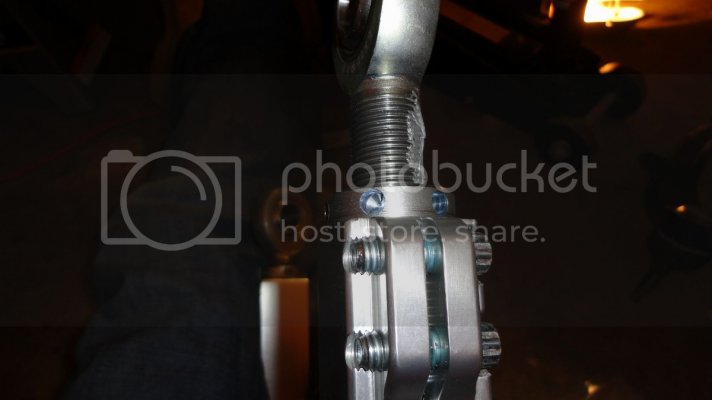
- Remove the heim joints and adjustment sleeves by hand and apply anti-sieze on all threads.
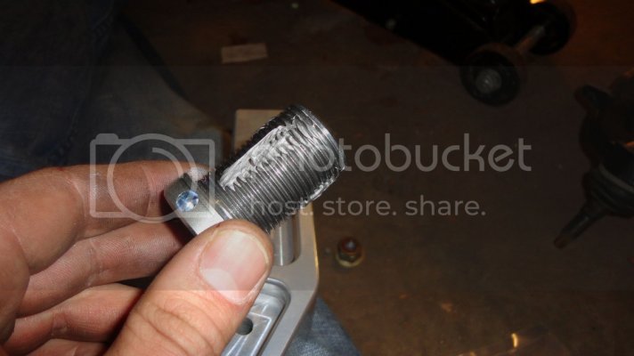
- Thread the adjustment sleeves and heim joints all the way in to the control arm.
- Adjust the UCA length by making 4 full turns out on the adjustment sleeves and heim joints. Make sure the the adjustment sleeve seams line up with the pinch seam joints.
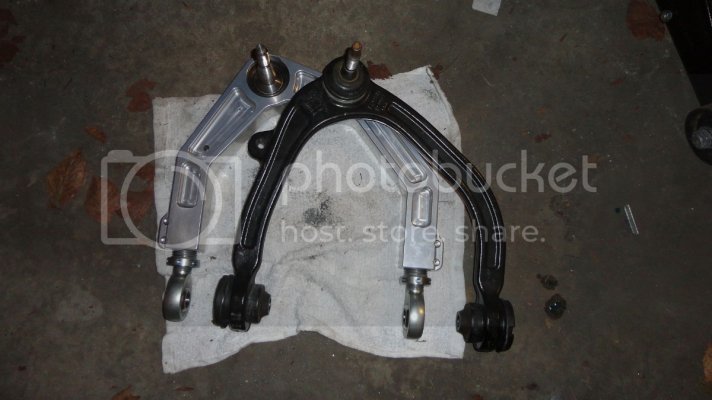
- Snug down pinch seam bolts until adjustment sleeve can't be turned by hand.
-Install the uniball pivot pin in to the control arm and tighten the the top cup bolt to 55 lb-ft using a 12pt 1/2" socket (use blue Loctite).
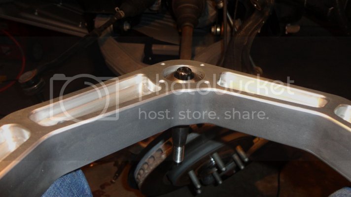
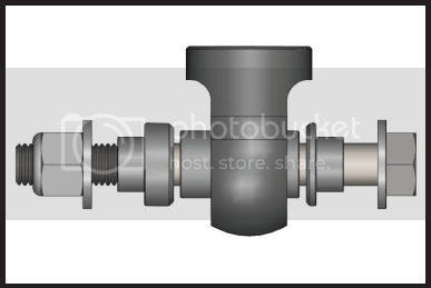
10. Install the ICON UCA to the frame in the following manner. The bushing spacers should be installed as shown with the larger of the two spacers on the outside of the arm. Place the factory UCA bolts through the spring bucket and control arm.
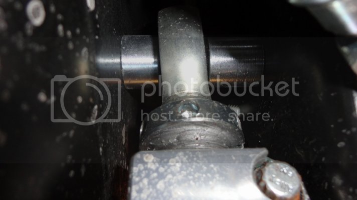
- Mount the remote reservoir bracket to the front UCA bolt as shown.
* The passenger side has a grounding strap secured to the spring bucket which needs to be removed and reinstalled through the machined hole in the bracket. (10mm socket)
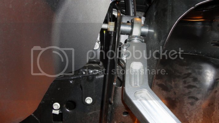
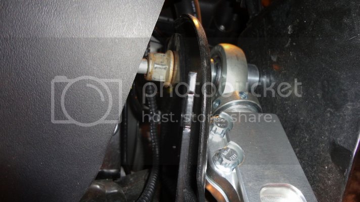
-Secure both nuts to the UCA bolts using a 21mm socket and 21mm wrench. Tighten to factory torque spec for these bolts which is 150 lb-ft.
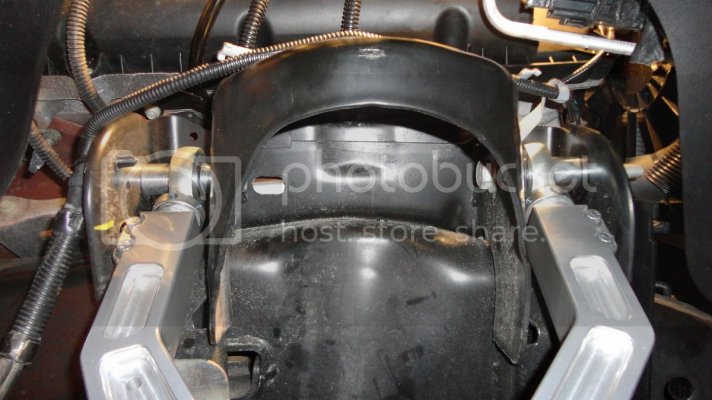
11.Begin installation of ICON 3.0 coilover.
- Safely route the remote reservoir and hose through the center hole of the spring bucket.
*Tip: Make sure the reservoir and hose is free to move while aligning shock for installation.
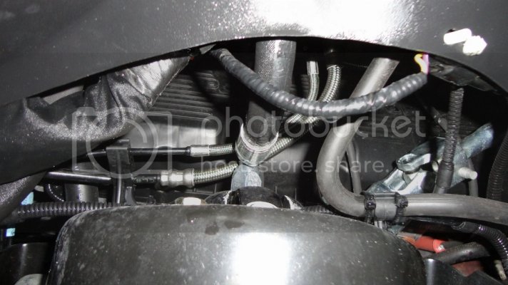
- Push the coilover up in to the spring bucket and loosely install the 3 top mounting bolts w/lock washers.
*Tip: The ICON shock top mounts are drilled for a specific side. Make note of mounting hole alignment to determine left or right.
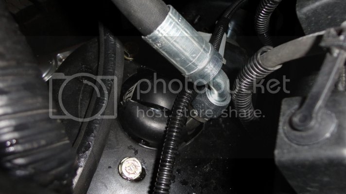
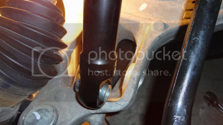
- Install spacers on the lower shock mount and lower control arm.
*Tip: larger spacers go on the side closest to the axle. Do not install lower shock mount bolt yet if you are also installing skid plates. If you are not installing the ICON skid plates then skip the next section. Align lower shock mount with lower control arm.
* Tip: The lower shock bolt and spacers are dissimilar metals and may seize to each other, so smear the shank of the bolt with plenty of anti-seize. This will save you a lot of trouble if you ever need to remove the shocks.
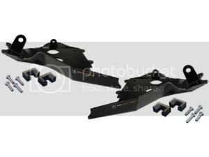
11a. Install the ICON lower control arm skid plates.
-Loosely install the supplied skid plate brackets as shown with the "flat" sides on of the U-brackets facing in.
*Tip: Use blue Loctite on the machine screws.
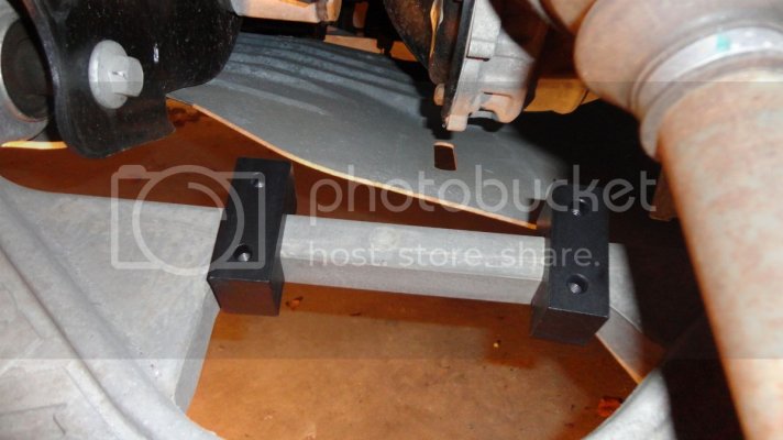
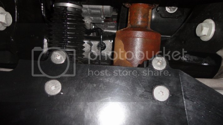
12. Secure ICON coilover. For now, loosely install the lower shock mount bolt, being sure to pass it through the outer skid plate mounting tab.
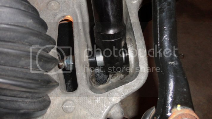
-Secure top shock mount bolts - straighten the coilover within the spring bucket and pull outward before snugging the bolts down. Firmly secure the bolts until the lock washers flatten out.
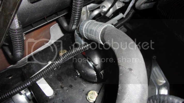
12a. Install lower sway bar link to control arm and skid plate. This is why we have left the lower shock mount bolt and U-brackets loose until now. Align the inner skid plate mounting tab with the sway bar mounting hole on the lower control arm. Place the supplied washer between the skid plate tab and control arm. Pass the sway bar link stud through the control arm and skid plate mounting tab then secure the nut.
*Tip: The additional space taken by the skid plate mounting tab will not allow the nylon insert to reach the threads on the sway bar stud so blue Loctite is recommended.
*Tip: Use a 6" socket extension with a pivoting socket adapter to ease any trouble in reaching the sway bar link bolt (18mm socket).
- Align and secure the skid plate U-bracket machine screws using an Alan wrench.
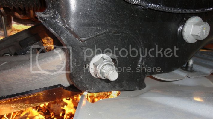
- Secure lower shock mount bolt using 15/16" wrench(bolt) and 15/16" socket(nut). Torque to 120 lb-ft.
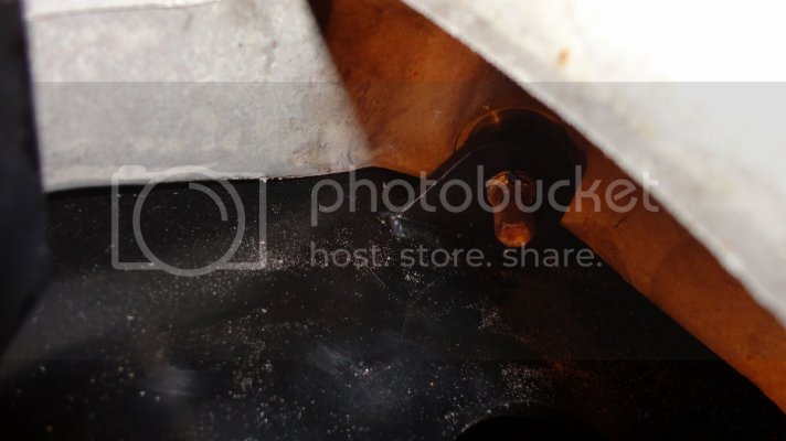
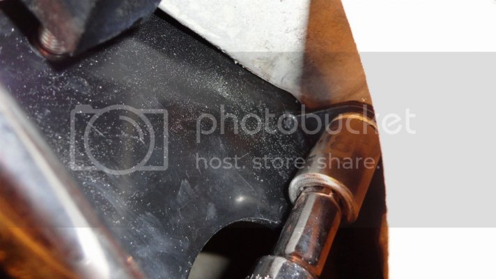
13. Re-install tie rod. Tighten until stop with 21mm wrench.
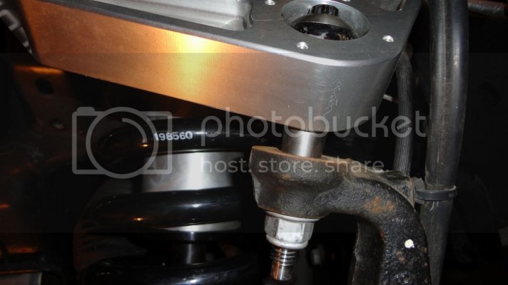
14. Install UCA pivot in to spindle. Push pin in to spindle until and tighten until stop when taper is pressed in to spindle mount.
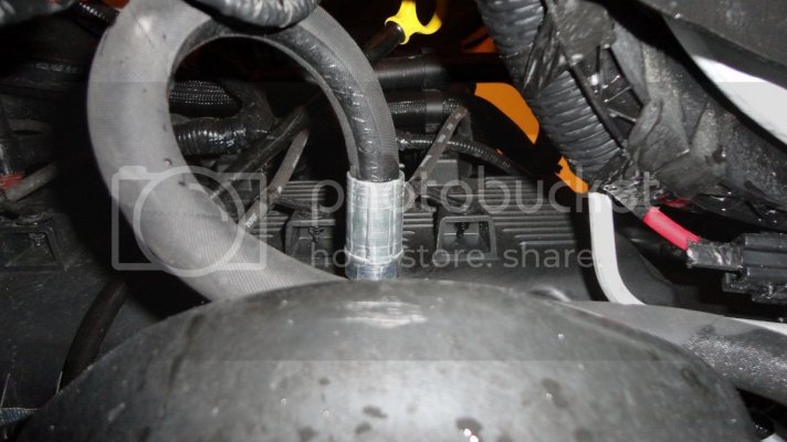
15. Route the reservoir hose up and twist to position the reservoir toward the front of the spring bucket. Secure the reservoir using the supplied hose clamps with a 5/16" nut driver.
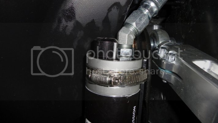
16. Install the o-ring and uniball cap to the UCA using the supplied Alan screws. * Use anti-seize and do not over-tighten.*
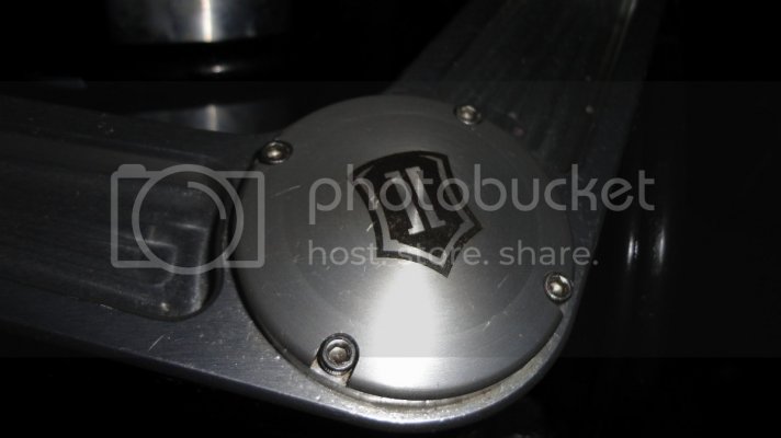
- Tighten down pinch seam bolts using a 12pt 3/8" socket with 1/4" driver. Snug down until the bolts no longer turn easily with one hand. *Do not over-tighten.*
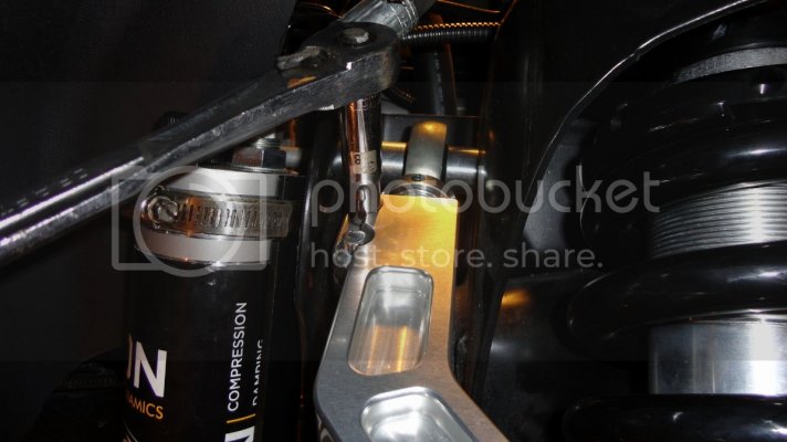
17. Re-secure lines/conduit to UCA, brackets and coil bucket using zip ties using good automotive practices.
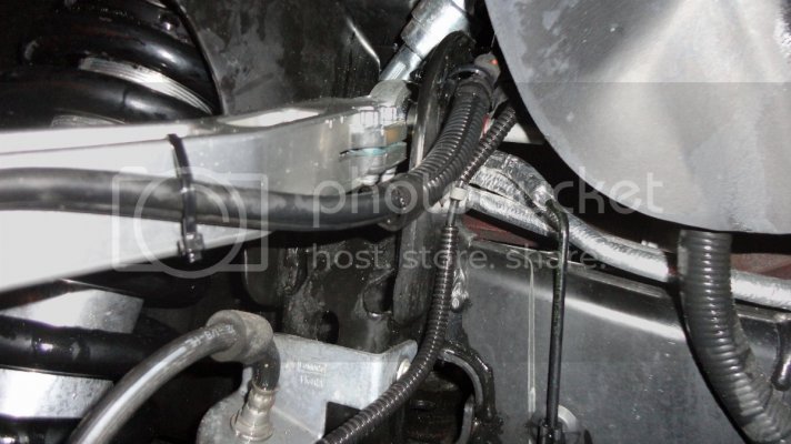
18. Now do a sweep of your install and make sure you have tightened down all bolts. Go for a short ride to allow the suspension jounce and settle. Measure the distance between the center line of the hub (wheel center cap) and the bottom lip of the fender flare. A general reference of height is as follows:
26.25" = "Middle perch height"
26.5" = ICON setting from factory - "visual level"
27" = Highest recommended setting for 2012+ Raptor (anecdotally speaking)
27.5" = "Top perch height"
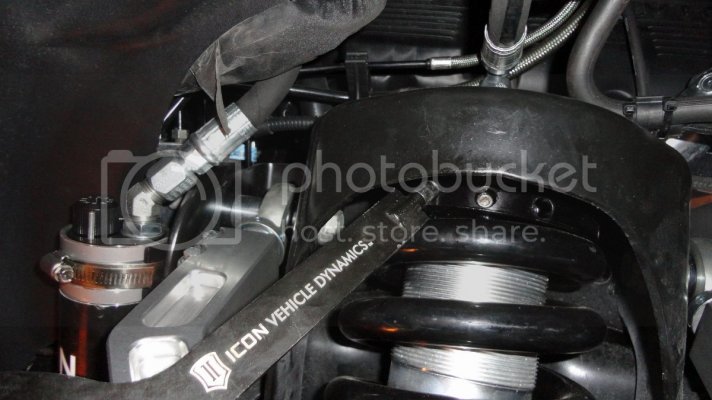
19. To adjust the ride height:
- Loosen Alan set screw
- Using the supplied spanner wrench, turn the coil spanner.
* Turn the spanner to the left to raise the height. Turning to the right will lower the height. Make sure to adjust the height equally on both sides and the set screw must be accessible after adjustment.
20. Alignment. Your truck will likely be out of camber, caster and toe. Depending on your final ride height, if you adjusted the upper control arm as instructed, you will have a positive camber prior to alignment (top of tire further out than the bottom). The alignment tech will be able to adjust the upper control arm if necessary but most of the camber can come out of the lower control arm to bring the bottom out to meet the upper. This is much easier and will help to retain the wheel track width which is lost when raising ride height.
The work is worth it! Please feel free to ask any questions or make remarks if I made any mistakes or omissions!
