¡Más! Factory Upfitters & Easy Access wiring!!
Ive gotten some requests for more info on my upfitter setup, so here it is…
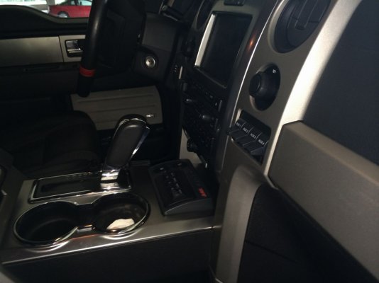
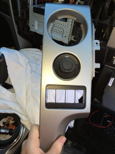
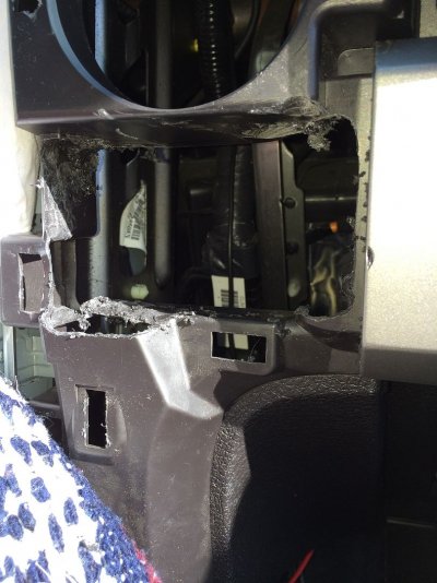
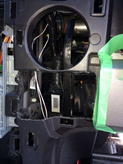
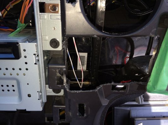
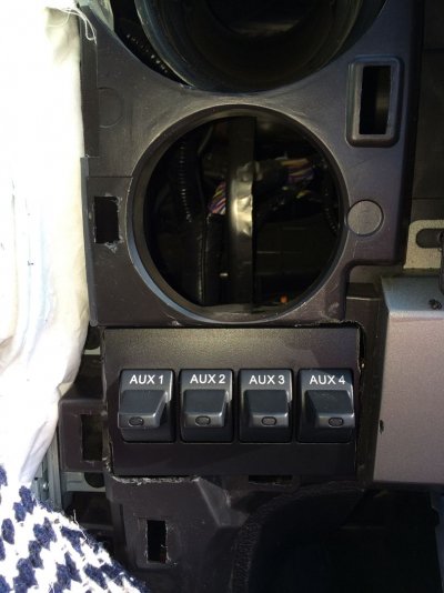
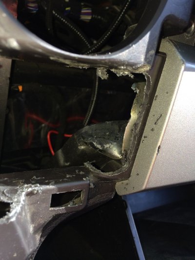
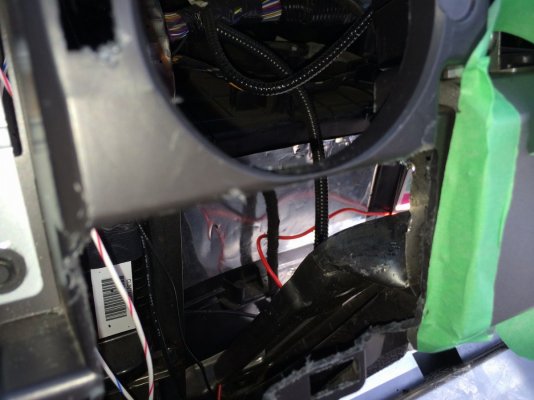
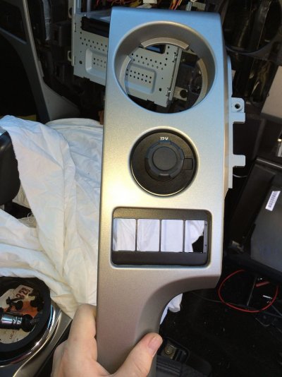
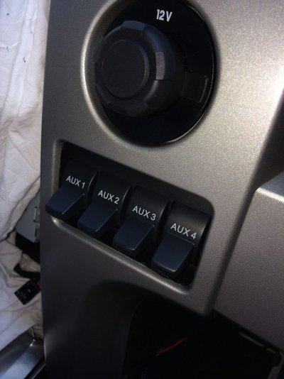
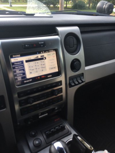
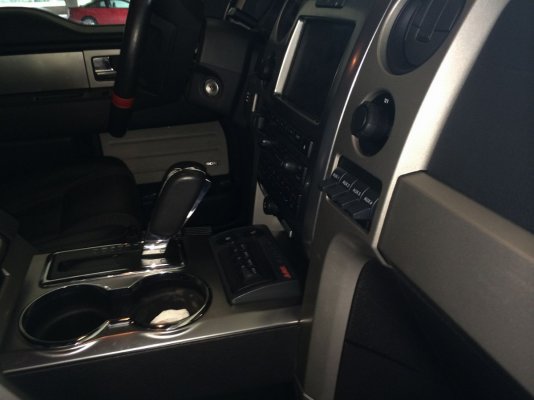
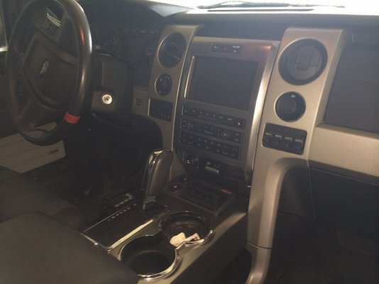
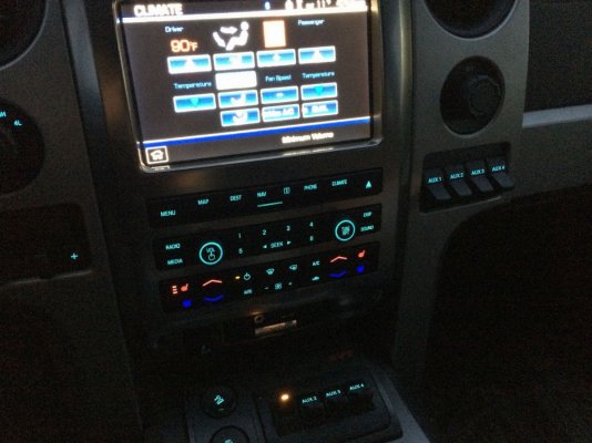
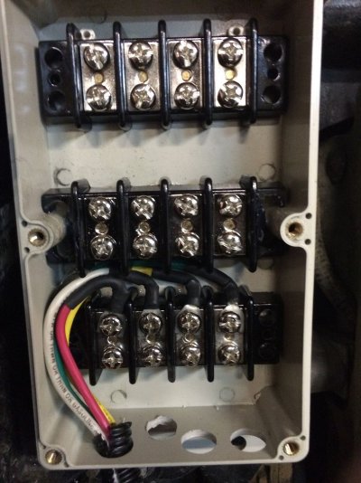
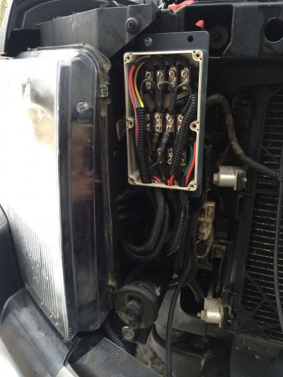
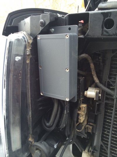
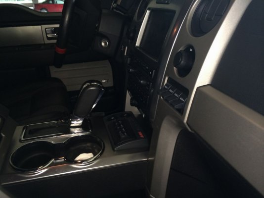
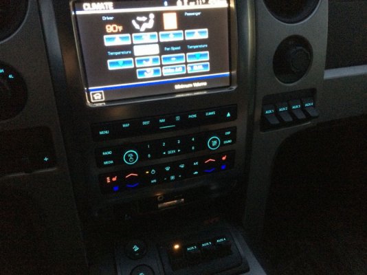
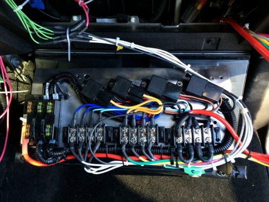
Like many others with light addictions I ran out of switches in short time, I wanted to add an extra bank of factory upfitters in a clean OEM looking fashion. The storage nooks beside the center stack were winners in my eyes for a location, as all they provided so far was a location for my chapstick to melt. Since the factory installed switches come fused and relayed, this would also be needed for the new switches. Also, considering that I have changed my lighting setup 3 times this year, I also decided to make things more easily accessible to change for future upgrades by adding a forward mounted wiring junction box.
So there are basically 3 individual DIYs here, should you choose to use 1, 2 or all parts in your own project.
The Plan:
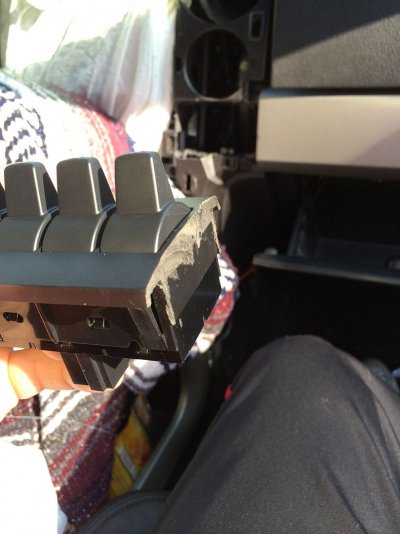
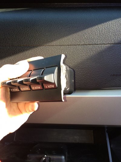
** Additional factory upfitter switch bank mounted in the dash console storage nook **
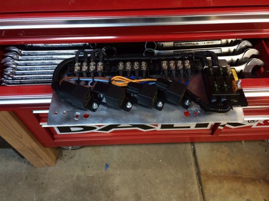
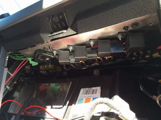
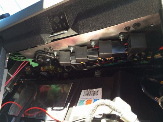
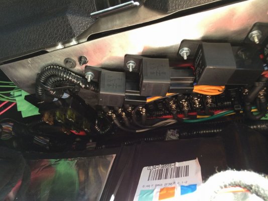
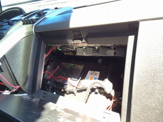
** Easy access relay panel for the new upfitters switches**
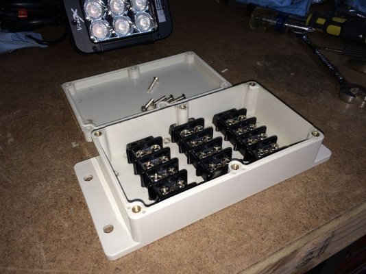
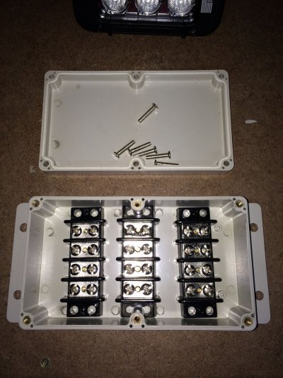
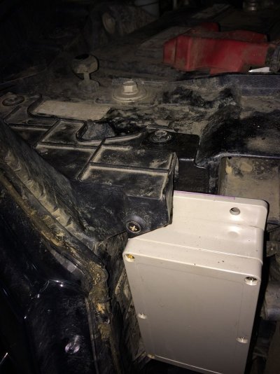
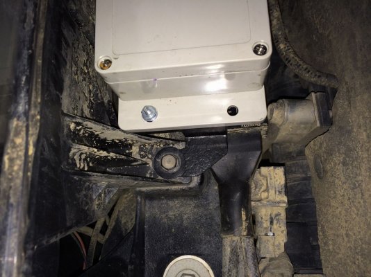
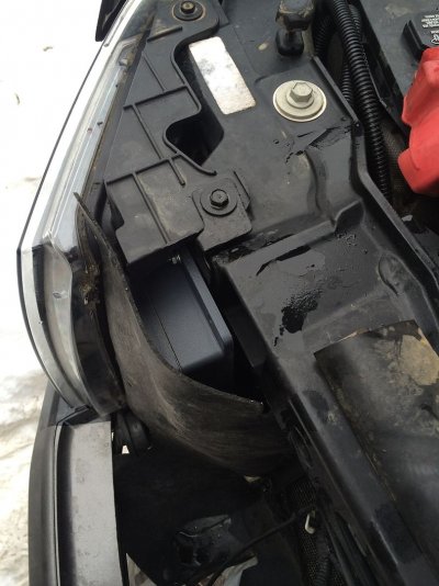
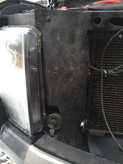
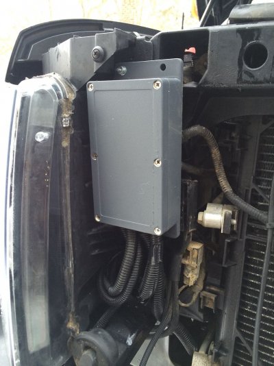
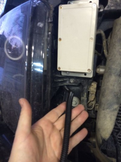
** Forward mounted Easy access Junction box**
Switches1
Switches2 lit up
Relaypanel1
Relaypanel2
juncbox1
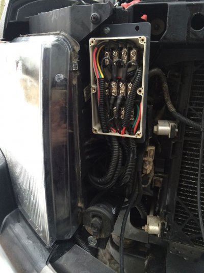
[juncbox2 with cover plastidipped]
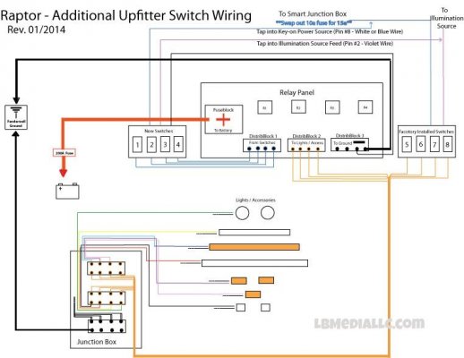
Wiring diagrams & Templates (See end for parts list):
Complete Setup
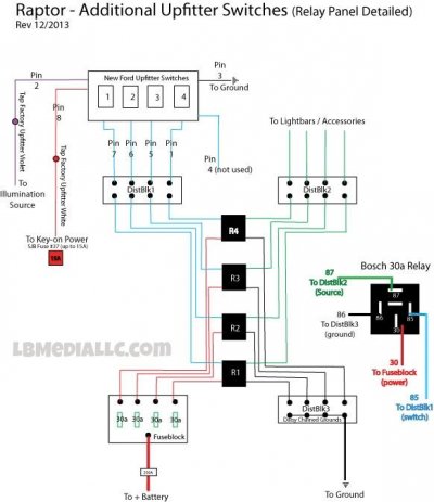
Relay Panel Detailed
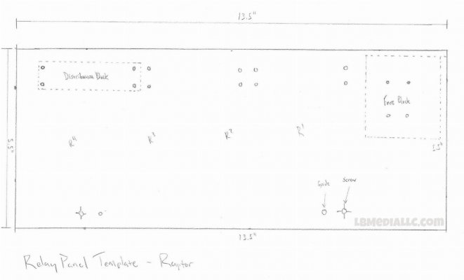
[Rely Board Template]
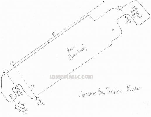
[Junction box bracket template]
*****************************************************
PART 1 - Relay Panel & Switch Wiring
Relay Panel
Pic Mounted
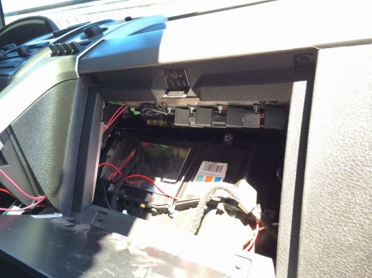
Pic exposed
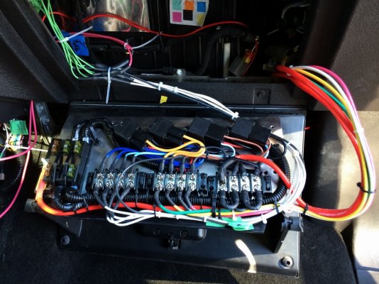
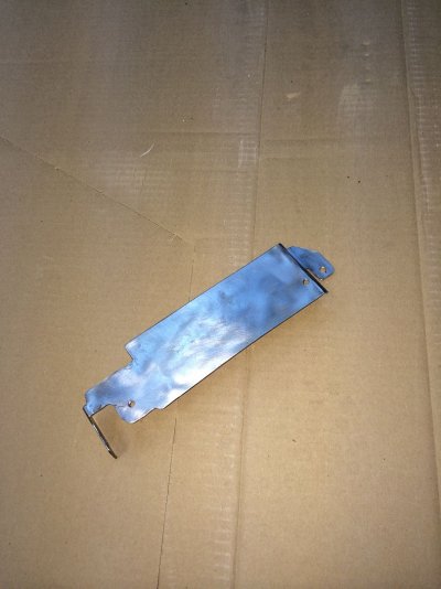
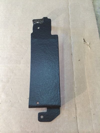
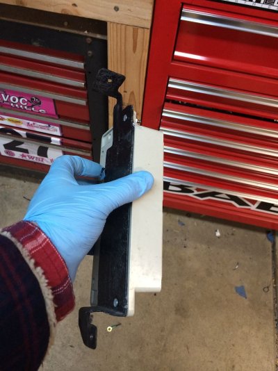
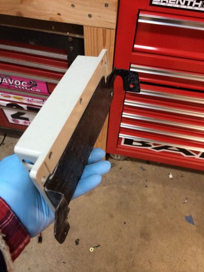
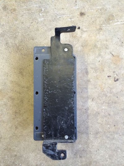
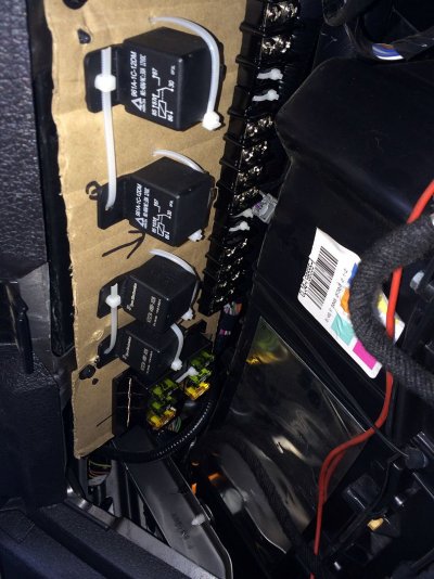
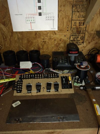
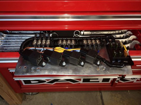
Skies the limit on your panel design, I used a 16ga sheet cut to ~5.5”x13.5”. Above is a printable template should you want to use this design (Confirm the measurements on the template pages are true after printing this out). **Since you’re already cutting sheet metal, If you plan to use a forward junction box and like my location, that template is also included above (this will come into play later).
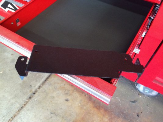
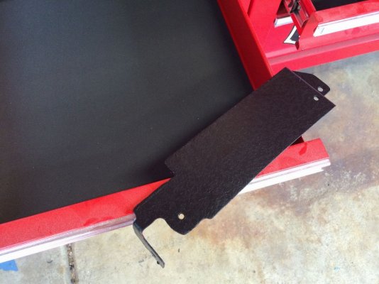
The relay panel will be bolting to the underside of your dash, behind the airbag and above the glove compartment. It is easily accessed by fully opening the glove compartment door. You will reuse two factory dash 8mm screws. The 2 outside holes on the panel plate are for the mount screw holes, the 2 inner holes are for the dash guide studs. The bend I went with is approx. 15 degrees and helps tuck the panel up further. Mock up the panel bare to confirm best fitment, I initially made my template from cardboard but this template should fit.
Cardboard installed
Card vs metal
Panel1
Panel2
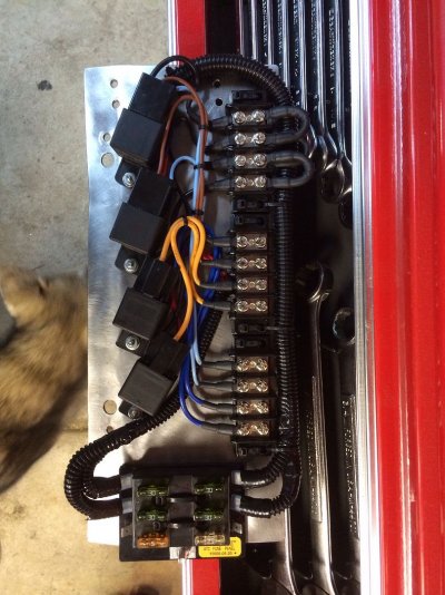
*With relays, fusebox, and distribution blocks installed on panel (See diagrams above), install panel under the dash to confirm there are no clearance issues with the glove box and its typical daily contents.
Panel3
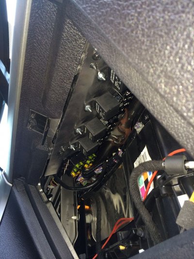
*If all is clear from glovebox door interference and your happy with how it fits, put this panel off to the side for later…
Switch Harness Wiring
Using your Ford 3U2Z14S411DLB Harness (OEM connector for the factory Upfitter switch bank), begin to label the wires. The Plastic harness connector specifies the wiring (pin) numbers. Summarized from the diagrams above:
Pin1 – Switch 1 (relay panel DistBlock 1)
Pin2 – To illumination source (Tap pin 2 [violet wire] from factory upfitter switch harness)
Pin3 – To ground (relay panel DistBlock 3)
Pin4 – NOT USED
Pin5 – Switch 2 (relay panel DistBlock 1)
Pin6 – Switch 3 (relay panel DistBlock 1)
Pin7 – Switch 4 (relay panel DistBlock 1)
Pin8 – To Key-on Power (Tap pin8 [blue wire on my ’12, ’10 Ford Schematic says white]on factory upfitter switch harness). Also at the Smart Junction Box(inside cabin fuse box), change fuse #41 from 7.5a to 15a(this is the fuse for the factory switch block itself) )
Relay Fuse FYI – on my ’12, factory upfitter relays ad fuses are located in the underhood fuse box
Upfitter #1 – 30a (fuse #18)
Upfitter #1 – 30a (fuse #19)
Upfitter #1 – 15a (fuse #44)
Upfitter #1 – 10a (fuse #28)
Labeled wires
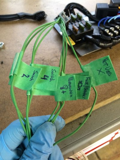
The switch block will end up being >1ft from the panel (assuming you’re using the right side nook, if using left nook add necessary length), so extending pin 1,5,6, 7 (switches), and pin 3 (ground) another 1-2 feet should suffice, adding eyelet connectors to these ends to connect to the panel. Pin 2 & 8 sources are also fairly close as well, so extending these a few feet as well.
Extended harness
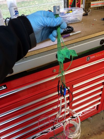
Once harness wiring has been extended, laying out the relay panel on passenger floor (or back side of glove box) worked easiest for me.
Panel on glove box door
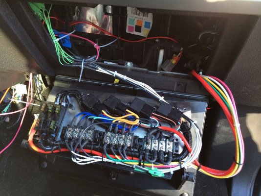
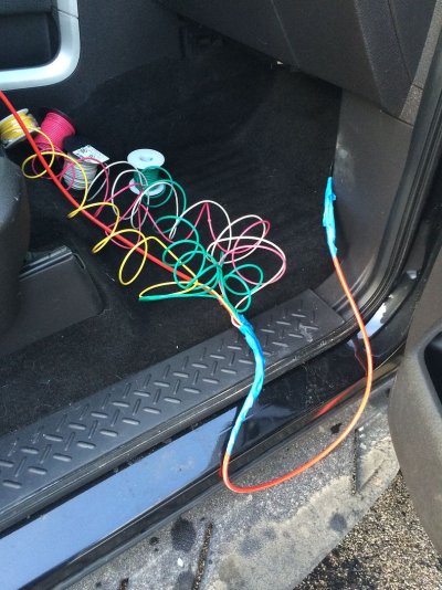
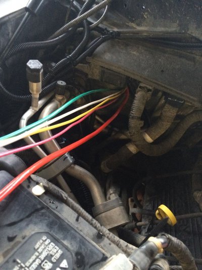
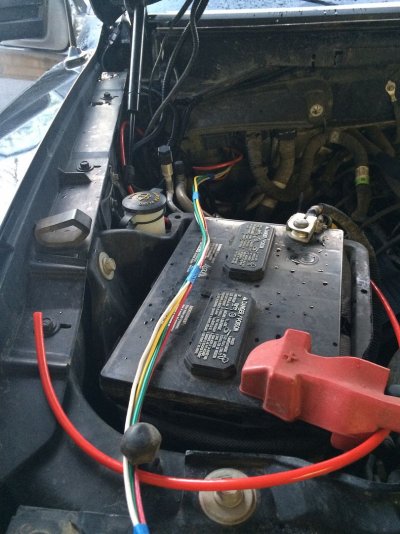
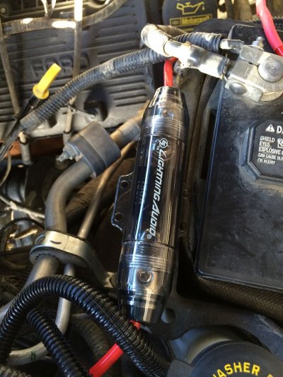
* Fish the 4 power wires from Distblock 2 to the forward mounted junction box (or near your lighting if not using a JunctionBox), leaving some additional length is helpful. Fish the single Power wire from the Fuse Block to the + battery terminal, and single ground from DistBlock 3 to the fenderwall ground. For the consolidated Power & ground lines, I used 8awg wire and a large 200a wafer style fuse before the battery.
Tip: I fed the 8awg power line through the firewall (below the ecu foam cover), taped the source wires to it,and pull it back into the engine bay with the sources.
fished wire pics
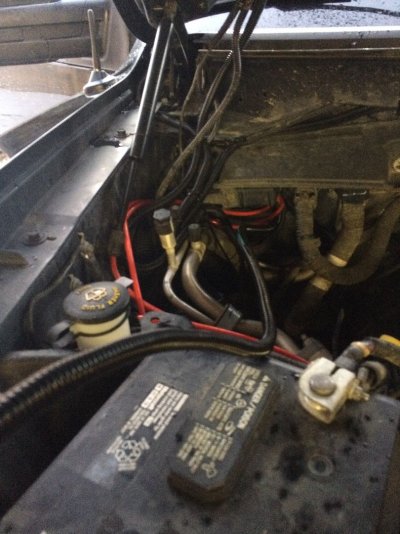
Fished to junc box mounted
wafer fuse
[fenderwall ground pic]
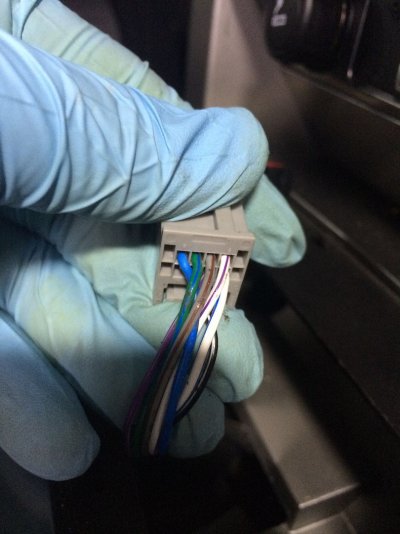
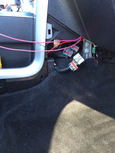
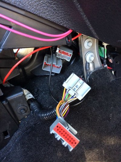
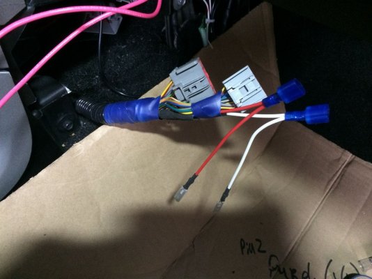
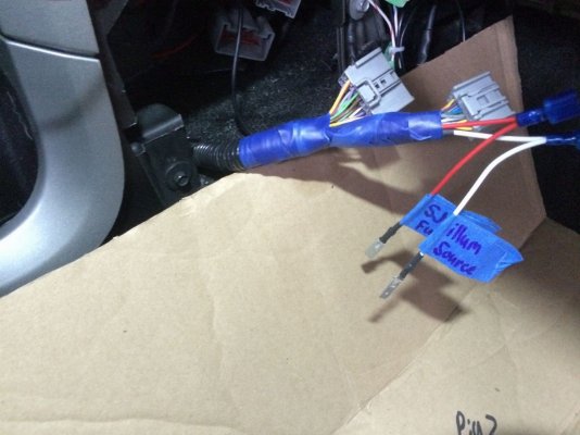
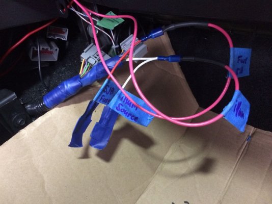
*For Pin 2 & 8 on your new harness, I tapped the factory upfitter switch harness #2 & #8. Remove the switch block from center console to expose harness connector. Note the color of wires on pin # 2 & 8 (you can tap here, but continue to hear another tap location). With center console side panel removed at passenger floor, unplug the 2 grey factory harness connectors. The smaller plug contains the 2 wires needed, tap the respective color plug that you found near the switch connector. For mine, pin 2 was Violet, the illuminatioin source. Pin 8 was blue, the power source (2010 ford wiring diagram stated it was white).
switch removed, wires exposed
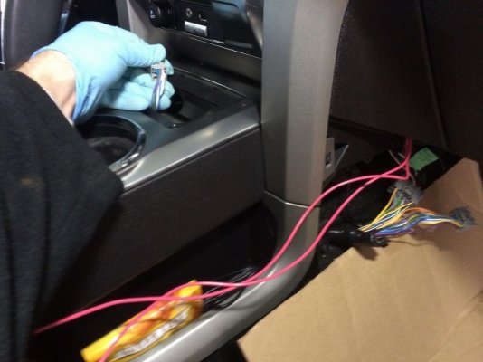
Connector up close
side panel removed
Harness unplugged
Harness Exposed
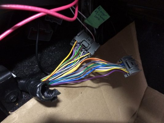
Since I was in there I tapped these sources with additional feeds, should I need them down the road. Not necessary though.
Harness tapped
*The factory upfitter switch bank is fused in the Smart Junction Box, fuse #41. It is fused at 7.5A, and since we have added a second bank we will up this fuse to 15A. Keep in mind this is just the fuse for the switch blocks themselves, not the switch sources (lights/accessories/etc)
[SJB fuse pics]
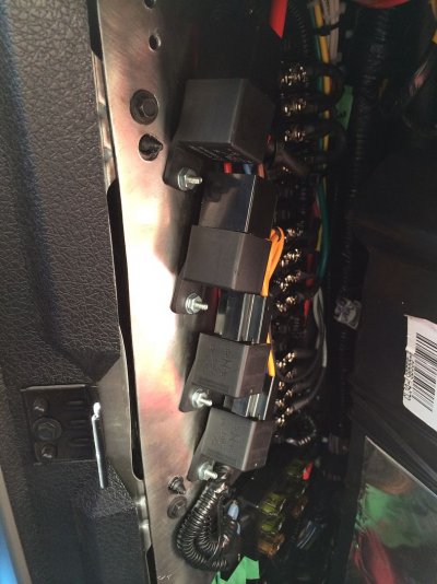
*Connect eyelets & slip connectors to respective distribution & fuse blocks wires. Zip tie wiring tight and snug to the panel accordingly & mount panel to the underside of the dash, securing with the factory 8mm screws
*Mount panel up
Ive gotten some requests for more info on my upfitter setup, so here it is…
Like many others with light addictions I ran out of switches in short time, I wanted to add an extra bank of factory upfitters in a clean OEM looking fashion. The storage nooks beside the center stack were winners in my eyes for a location, as all they provided so far was a location for my chapstick to melt. Since the factory installed switches come fused and relayed, this would also be needed for the new switches. Also, considering that I have changed my lighting setup 3 times this year, I also decided to make things more easily accessible to change for future upgrades by adding a forward mounted wiring junction box.
So there are basically 3 individual DIYs here, should you choose to use 1, 2 or all parts in your own project.
The Plan:
** Additional factory upfitter switch bank mounted in the dash console storage nook **
** Easy access relay panel for the new upfitters switches**
** Forward mounted Easy access Junction box**
Switches1

Switches2 lit up

Relaypanel1

Relaypanel2

juncbox1

[juncbox2 with cover plastidipped]

Wiring diagrams & Templates (See end for parts list):
Complete Setup

Relay Panel Detailed

[Rely Board Template]

[Junction box bracket template]

*****************************************************
PART 1 - Relay Panel & Switch Wiring
Relay Panel
Pic Mounted

Pic exposed

Skies the limit on your panel design, I used a 16ga sheet cut to ~5.5”x13.5”. Above is a printable template should you want to use this design (Confirm the measurements on the template pages are true after printing this out). **Since you’re already cutting sheet metal, If you plan to use a forward junction box and like my location, that template is also included above (this will come into play later).
The relay panel will be bolting to the underside of your dash, behind the airbag and above the glove compartment. It is easily accessed by fully opening the glove compartment door. You will reuse two factory dash 8mm screws. The 2 outside holes on the panel plate are for the mount screw holes, the 2 inner holes are for the dash guide studs. The bend I went with is approx. 15 degrees and helps tuck the panel up further. Mock up the panel bare to confirm best fitment, I initially made my template from cardboard but this template should fit.
Cardboard installed

Card vs metal

Panel1

Panel2

*With relays, fusebox, and distribution blocks installed on panel (See diagrams above), install panel under the dash to confirm there are no clearance issues with the glove box and its typical daily contents.
Panel3

*If all is clear from glovebox door interference and your happy with how it fits, put this panel off to the side for later…
Switch Harness Wiring
Using your Ford 3U2Z14S411DLB Harness (OEM connector for the factory Upfitter switch bank), begin to label the wires. The Plastic harness connector specifies the wiring (pin) numbers. Summarized from the diagrams above:
Pin1 – Switch 1 (relay panel DistBlock 1)
Pin2 – To illumination source (Tap pin 2 [violet wire] from factory upfitter switch harness)
Pin3 – To ground (relay panel DistBlock 3)
Pin4 – NOT USED
Pin5 – Switch 2 (relay panel DistBlock 1)
Pin6 – Switch 3 (relay panel DistBlock 1)
Pin7 – Switch 4 (relay panel DistBlock 1)
Pin8 – To Key-on Power (Tap pin8 [blue wire on my ’12, ’10 Ford Schematic says white]on factory upfitter switch harness). Also at the Smart Junction Box(inside cabin fuse box), change fuse #41 from 7.5a to 15a(this is the fuse for the factory switch block itself) )
Relay Fuse FYI – on my ’12, factory upfitter relays ad fuses are located in the underhood fuse box
Upfitter #1 – 30a (fuse #18)
Upfitter #1 – 30a (fuse #19)
Upfitter #1 – 15a (fuse #44)
Upfitter #1 – 10a (fuse #28)
Labeled wires

The switch block will end up being >1ft from the panel (assuming you’re using the right side nook, if using left nook add necessary length), so extending pin 1,5,6, 7 (switches), and pin 3 (ground) another 1-2 feet should suffice, adding eyelet connectors to these ends to connect to the panel. Pin 2 & 8 sources are also fairly close as well, so extending these a few feet as well.
Extended harness

Once harness wiring has been extended, laying out the relay panel on passenger floor (or back side of glove box) worked easiest for me.
Panel on glove box door


* Fish the 4 power wires from Distblock 2 to the forward mounted junction box (or near your lighting if not using a JunctionBox), leaving some additional length is helpful. Fish the single Power wire from the Fuse Block to the + battery terminal, and single ground from DistBlock 3 to the fenderwall ground. For the consolidated Power & ground lines, I used 8awg wire and a large 200a wafer style fuse before the battery.
Tip: I fed the 8awg power line through the firewall (below the ecu foam cover), taped the source wires to it,and pull it back into the engine bay with the sources.
fished wire pics


Fished to junc box mounted

wafer fuse

[fenderwall ground pic]
*For Pin 2 & 8 on your new harness, I tapped the factory upfitter switch harness #2 & #8. Remove the switch block from center console to expose harness connector. Note the color of wires on pin # 2 & 8 (you can tap here, but continue to hear another tap location). With center console side panel removed at passenger floor, unplug the 2 grey factory harness connectors. The smaller plug contains the 2 wires needed, tap the respective color plug that you found near the switch connector. For mine, pin 2 was Violet, the illuminatioin source. Pin 8 was blue, the power source (2010 ford wiring diagram stated it was white).
switch removed, wires exposed

Connector up close

side panel removed

Harness unplugged

Harness Exposed

Since I was in there I tapped these sources with additional feeds, should I need them down the road. Not necessary though.
Harness tapped


*The factory upfitter switch bank is fused in the Smart Junction Box, fuse #41. It is fused at 7.5A, and since we have added a second bank we will up this fuse to 15A. Keep in mind this is just the fuse for the switch blocks themselves, not the switch sources (lights/accessories/etc)
[SJB fuse pics]
*Connect eyelets & slip connectors to respective distribution & fuse blocks wires. Zip tie wiring tight and snug to the panel accordingly & mount panel to the underside of the dash, securing with the factory 8mm screws
*Mount panel up


Last edited:


