Should a diode be used with a relay from upfitter switch?

Disclaimer: Links on this page pointing to Amazon, eBay and other sites may include affiliate code. If you click them and make a purchase, we may earn a small commission.

2020Raptor

Full Access Member
Joined
Feb 11, 2020
Posts
318
Reaction score
155
Location
South Central...NJ
I'm sorry! I'm an electrical engineer so it's rare I can say anything knowledgeable here. Sometimes I get carried away. I was, however, telling my wife and daughter at the dinner table last night about the exciting diode discussion we were having on FRF. They think you are all nerds like me now. Sorry!

As a Chemical Engineer, I have many questions regarding diodes.
Thanks to everyone for contributing to my continuing education.
:D
 
Last edited:

2020Raptor

Full Access Member
Joined
Feb 11, 2020
Posts
318
Reaction score
155
Location
South Central...NJ
For what it's worth, allow me to clarify:

The light bar is connected to an upfitter switch, which has a relay somewhere, yes ?

According to FTO, a solid state relay would be the safest method of tapping into the high beam circuit.

So if wiring a second power supply to the light bar in that way:

Is a diode or something necessary on either power wire to prevent backfeeding the other circuit ?

Whew, thanks !
 

2020Raptor

Full Access Member
Joined
Feb 11, 2020
Posts
318
Reaction score
155
Location
South Central...NJ
I agree, after reading FTO's replies to me last year, and to several others since then, I don't think it's worth risking your BCM for the small convenience of having them tied to the high beam. Having off road aux lights tied into your high beams is also against many states inspection laws.

The circuit to energize the light bar with the high beam switch would be armed with an upfitter switch.
It will only be temporarily used that way as required.
I just need an easier method of turning on/off the light bar.

I find that I would like it on in many instances where I would otherwise use high beams.
Flicking the upfitter switch repeatedly gets tiresome quickly.

I could rig a different switch somewhere else that would be easier to access.
The high beam switch just seems the most convenient.
Or maybe and old school floor mounted high beam switch.
 

GordoJay

FRF Addict
Joined
Feb 8, 2020
Posts
7,488
Reaction score
16,106
Location
Colorado
For what it's worth, allow me to clarify:

The light bar is connected to an upfitter switch, which has a relay somewhere, yes ?

According to FTO, a solid state relay would be the safest method of tapping into the high beam circuit.

So if wiring a second power supply to the light bar in that way:

Is a diode or something necessary on either power wire to prevent backfeeding the other circuit ?

Whew, thanks !

There are several ways to wire it up. As I understand it, the upfitters don't have relays, but lots of folks recommend using one. I haven't looked at it and have no opinion. If you wire an upfitter directly to your light in parallel with your relay, you don't need a diode. Use an upfitter with extra current carrying ability, say a 20A switch for a 15A load. If you want to use a relay on the upfitter, you can run the upfitter switch to the input of the same relay that's on the high beam circuit. That way you only use one relay, but you need a diode to prevent backfeeding the high beam circuit. You can also use two relays wired in parallel, with the high beam circuit driving one and the upfitter driving the other, in which case you don't need a diode.
 

GordoJay

FRF Addict
Joined
Feb 8, 2020
Posts
7,488
Reaction score
16,106
Location
Colorado
The circuit to energize the light bar with the high beam switch would be armed with an upfitter switch.
It will only be temporarily used that way as required.
I just need an easier method of turning on/off the light bar.

I find that I would like it on in many instances where I would otherwise use high beams.
Flicking the upfitter switch repeatedly gets tiresome quickly.

I could rig a different switch somewhere else that would be easier to access.
The high beam switch just seems the most convenient.
Or maybe and old school floor mounted high beam switch.

You will need to use two of the upfitter switches to do this. One to arm the high beam trigger and another to turn the bar on independent of the high beams. I like the idea of the old-school floor mounted switch.
 

bryanb

Member
Joined
Aug 4, 2013
Posts
31
Reaction score
50
Location
Tyler, TX
So if wiring a second power supply to the light bar in that way:

Is a diode or something necessary on either power wire to prevent backfeeding the other circuit ?

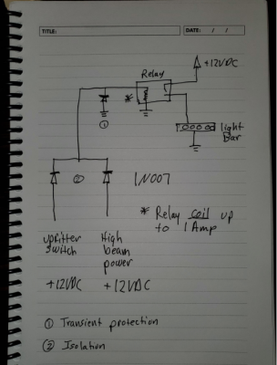
Ok, now I know what you are asking. The answer is you need diodes for both of the cases I originally described. You can use the same readily available 1N007 diode for all three diodes below.

You're getting lots of different advice including that diodes aren't needed at all. That may be right, but since you don't know what is driving the two input signals below (upfitter switch and high beam) the right way to combine the outputs of two different power sources is shown below. Normally those would be Schottky diodes (different part number) but for your application 1N007 will be fine. These are different power sources because they won't have the exact same voltage (two different paths from the battery) and the high beam especially may be driven by a solid state device which induces its own voltage drop relative to the 12 VDC source. Never connect two power supplies (or signals) directly together unless you know the drivers of those power supplies (or signals) are designed to support that. We don't know in this case.

The two lower diodes prevent one input from driving back to the other input's driver which is very important if the other input is a solid state device. If both inputs are driven by mechanical relays then this would be less important to do, but the conservative design approach is to assume the worst case.

The top diode is used to protect the rest of the circuit from the transient voltage that is induced when the relay is turned off. Some automotive relays have these built in. Since you don't know, use the conservative approach. These diodes probably cost less than 20 cents each in small quantities so adding them is no big deal.

This diode selection is fine as long as the steady state COIL current of the automotive relay in the picture does not exceed 1 A. Most are well under 0.5 A.

Use at your own risk. This is not offered as professional engineering advice.


upload_2021-1-27_9-42-17.png
 

The Car Stereo Company

aka grumpy car stereo guy and frf rolodex
Supporting Member
Joined
Jul 8, 2012
Posts
32,646
Reaction score
23,710
Location
here, on frf
I am not following you.
What is an "lvt" ?
low voltage trigger. your solid state relay. i would use it as just a trigger to power a standard relay. the aux switches do in fact have relays, however they arent your standard spdt relay and you cant tie into them.
 

2020Raptor

Full Access Member
Joined
Feb 11, 2020
Posts
318
Reaction score
155
Location
South Central...NJ
Ok, now I know what you are asking. The answer is you need diodes for both of the cases I originally described. You can use the same readily available 1N007 diode for all three diodes below.

You're getting lots of different advice including that diodes aren't needed at all. That may be right, but since you don't know what is driving the two input signals below (upfitter switch and high beam) the right way to combine the outputs of two different power sources is shown below. Normally those would be Schottky diodes (different part number) but for your application 1N007 will be fine. These are different power sources because they won't have the exact same voltage (two different paths from the battery) and the high beam especially may be driven by a solid state device which induces its own voltage drop relative to the 12 VDC source. Never connect two power supplies (or signals) directly together unless you know the drivers of those power supplies (or signals) are designed to support that. We don't know in this case.

The two lower diodes prevent one input from driving back to the other input's driver which is very important if the other input is a solid state device. If both inputs are driven by mechanical relays then this would be less important to do, but the conservative design approach is to assume the worst case.

The top diode is used to protect the rest of the circuit from the transient voltage that is induced when the relay is turned off. Some automotive relays have these built in. Since you don't know, use the conservative approach. These diodes probably cost less than 20 cents each in small quantities so adding them is no big deal.

This diode selection is fine as long as the steady state COIL current of the automotive relay in the picture does not exceed 1 A. Most are well under 0.5 A.

Use at your own risk. This is not offered as professional engineering advice.


View attachment 160670

Thanks very much for the diagram.

This is what I think that I am trying to accomplish:

Upfitter switch 1 for direct power.

Upfitter switch 2 to arm the circuit with the ss relay that will be triggered by the high beam switch.

Make sense, or am I missing something ?

Thanks again.
 
Last edited:

bryanb

Member
Joined
Aug 4, 2013
Posts
31
Reaction score
50
Location
Tyler, TX
Make sense, or am I missing something ?

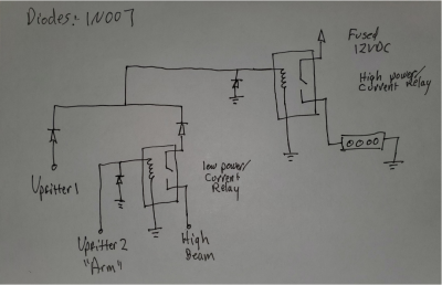
I modified my diagram to add your "arming" function:

upload_2021-1-28_10-45-48.png


The primary issue with your design is that you've put the diodes on the high current path. My diodes are all on the low current paths so they will be small and won't have thermal design constraints to worry about.

If your light bar is high amperage (it is!) then the diodes you'd need for your circuit are quite beefy. You'll need to properly cool them because they will dissipate a lot of heat. Being in the engine compartment you've got de-rating concerns to take in to consideration. (Current-carrying components are good for the rated values only within a given temperature range. You'll have to start de-rating and upsizing the diodes to account for this in the engine compartment, so it is best to avoid these problems entirely by keeping the current through the diodes low.)

To support the arming function I added a small relay. It's current carrying capacity can be as small as you can find in an automotive relay. Make sure the relay controlling the light bar is sized for the current draw of the light bar plus some margin.

The other problem with your high-current diode solution is that the silicon diodes will drop the voltage the light bar sees by 0.7V. In a 12 V system, that's significant and results in the LED driver drawing a higher current to deliver the same power to the LEDs. Higher current always means more component stress and shorter lifetimes even if the LED driver is rated to operate at down to 11.3 VDC (ratings always assume a MTBF and not that the device can operate at one extreme of the rated values forever). This voltage drop can be reduced by using a different kind of diode, but that's still the wrong approach.

If you want to add a safety feature to help reduce the possibility that a failure in this circuit cascades to take out your headlights (or high beams) then add a 1A slow blow fuse to the "high beam" signal at the point where you tap it. No guarantees, of course... :)
 
Last edited:
Top