This brace kit is close to what I want/need for my Raptor. The hardened bolt crossing through the frame and creating a load bearing spot is my concern because it could "tear" through the frame steel under impact; if it is actually carrying a load?
The silver hardware is grade 5, zinc galvanized. The gold hardware is grade 8, zinc chromate, I believe.
Gotcha. I think you're probably right on the nut.
Just to be really really clear (and you may already understand this), the bolt does
not cross through the frame. It passes through the outboard side of the box, and the nut is affixed to that bolt inside the frame; in other words, the bolt passes through only one wall of the frame (the outside), not two walls (the second being the inside wall). So what you have here is a clamping action between the RPG mount, and one wall of the frame.
To my knowledge and understanding, the bolt is not a significant load bearing part of the design; its primary purpose is to hold the mount on, and resist its twisting while under load.
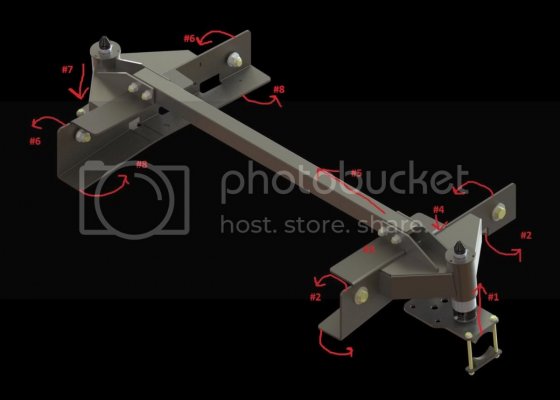
Here, I've tried to draw what's going on to the best of my understanding. (I gots the mad photoshop skilz!). I'll reference the numbers in the pic within the text below

As load is applied (#1), the mount will want to twist up and inward (#2). It cant twist however because of the top plate (#3) and those bolts holding the mount onto the frame, and so the load is spread along the mount's top wall and the frame its in contact with. Those bolts we're talking about basically stop the mount from just twisting right off, and if I had to guess, that "sheering" stress is why grade 8 bolts were selected. That's where their strength comes in.
But as load increases, that twist stress increases. As the load pushes up (#1), that top wall presses down harder and harder (#4). At this point in the discussion, the only thing stopping that twisting stress from basically collapsing the frame on top (#4) is the frame itself.
And that's where that cross brace comes in. Before stresses get anywhere near the failure point of the frame, that brace has spread and transferred the load over to the opposite side (#5). So on the other side you have the outside wall wanting to twist down (#7) and off the outside wall (#6), but it is prevented from doing so because the bottom of the mount is now spreading the load to along the bottom of the frame wall its in contact with (#8).
I hope that makes sense. Its hard to describe, but as I understand it, the load that used to be focused on one silver dollar sized spot, under a crumple zone on the frame has now been spread out to like 48 square inches of surface area on top of that crumple zone, as well as like 96 square inches of bottom frame on the opposite side, and all the secondary contact points between here and there (totally rough guesses based on my eyeball measurements).
RPG, by all means please correct me in anything I've said wrong. I'm just trying to explain what was explained to me.


