Pass Thru Wires / Upfitter Switches Explained (Video)

Disclaimer: Links on this page pointing to Amazon, eBay and other sites may include affiliate code. If you click them and make a purchase, we may earn a small commission.

MagicMtnDan

FRF Addict
Joined
Oct 28, 2011
Posts
7,661
Reaction score
1,795
Location
Magic Mountain
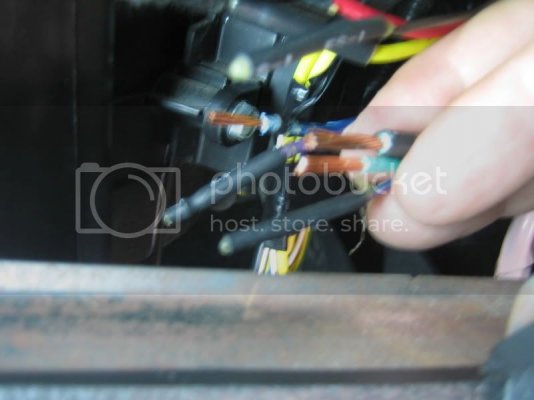
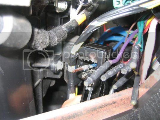
You can see several of the wires have been stripped:
IMG_2945.jpg

Here's a picture of one of the wires after I stripped it. You can see the wire stripper I used (this one is made by Klein, available at Home Depot for about $25 - I like this one a lot more than the one sold at Lowes).
IMG_2943.jpg

You can see how the ends of the wires are covered by the wire end terminations provided from the factory.

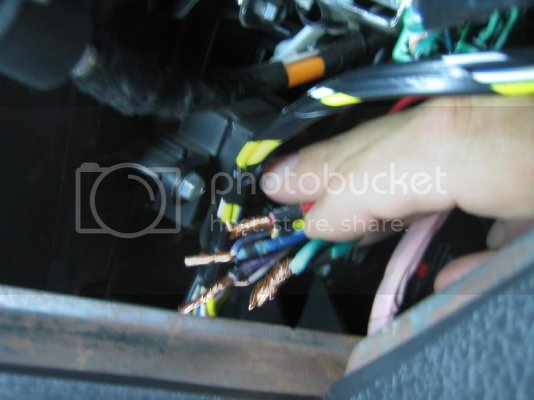
This picture is looking through the glovebox opening (glovebox completely removed) - I inserted my hand through the opening in the right end of the IP (instrument panel/dashboard) accessed by removing the panel.

You can see the wires have all been stripped and twisted together ready for soldering. I used heat shrink tubing to cover the 4 wire connections.
IMG_2949.jpg
 

MagicMtnDan

FRF Addict
Joined
Oct 28, 2011
Posts
7,661
Reaction score
1,795
Location
Magic Mountain
Grounding

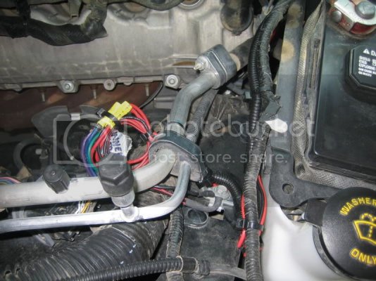
Underhood, close to the location where the 4 wires (Red, Green, Blue, Purple) are located, are two silver color metal tubes/pipes of different size. These appear to be HVAC tubes. Holding them in place is a metal retaining bracket that is screwed to the Raptor body (metal). This was the best and easiest location for me to use as a ground.

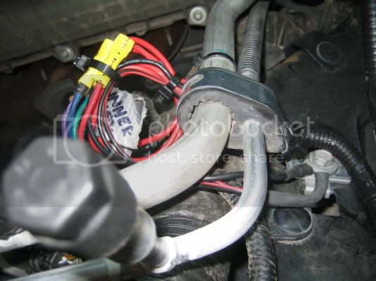
I unscrewed the bolt and removed it. The connectors on the two ground wires provided by Rigid Industries (the Duallys' grounds are connected together so I had two ground wires - one for the Duallys and one for the 20" lightbar) are just big enough (almost too small) to go around the bolt. I screwed the bolt to get the connectors to move up the threads and once they were under the bolt head I reinstalled the bolt in the bracket and tightened it down.

You can see the location of the bolt, the bracket and the two silvery tubes (to the left of (behind) the windshield fluid container) as well as the ground wires:

IMG_2951.jpg

You can see the bolt with the two connectors held securely in place between the bolt head and the metal bracket. I used butt (crimp) connectors (the yellow things) to connect the factory provided underhood switch wires to the lights' wires. You can see a label for the two pairs of Dually lights I made using duct tape and a Sharpie (one says "Inner" and the other says "Outer"):

IMG_2952.jpg
 

MagicMtnDan

FRF Addict
Joined
Oct 28, 2011
Posts
7,661
Reaction score
1,795
Location
Magic Mountain
This thread should also include Jason's excellent graphic which provides a lot of info.

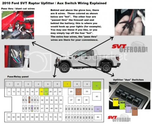
Below: Here's Jason's graphic providing an overview of the Upfitter switches, fuses, relays and pass-through wires:

SVTOffroadcom-JasonsUpfitterpic01co.jpg


Below: In this cropped version of the above pic, look at the image on the right showing the swtiches (1-4) and the wire colors next to them. These are the colors of the four wires that originate at the Upfitter switches and end behind the glovebox. Those four wires need to be connected to the "Pass-Thru Wires" that also are behind the glovebox and they "pass-thru" the firewall and into the engine compartment where they terminate on top of the passenger side wheel well close to the hood strut.

SVTOffroadcom-JasonsUpfitterpic02.jpg
 

Falcon

Full Access Member
Joined
Mar 22, 2010
Posts
876
Reaction score
5
Location
Ozarks
GREAT stuff guys. One question that I haven't seen discussed: What is the max amperage on the upfitters? Since one is fused at 30 amps, does that mean that ALL the switches and wiring are good for 30 amps? Just a matter of changing fuses?

Falcon
 

MagicMtnDan

FRF Addict
Joined
Oct 28, 2011
Posts
7,661
Reaction score
1,795
Location
Magic Mountain
I'm not an electrical guy so I'll let someone else answer. I can tell you that the wire gauge on Upfitter switch #4 is thinner than the others so I doubt that's a good idea (increasing amperage of fuses).
 

Xjrguy

FRF Addict
Joined
Aug 8, 2010
Posts
1,331
Reaction score
12
GREAT stuff guys. One question that I haven't seen discussed: What is the max amperage on the upfitters? Since one is fused at 30 amps, does that mean that ALL the switches and wiring are good for 30 amps? Just a matter of changing fuses?

Falcon


No!

All the EXTERIOR to the cab wiring in the engine compartment (RED, GREEN, PURPLE, and BLUE) in the wiring loom designated for the upfitter switches is fairly burly copper cable and matches the gauge of Upfitter switch 1 & 2. That means that all the underhood connections could support the higher amperage draw (30A of switch 1 & 2) and are the same heavier gauge wiring.

HOWEVER, as mentioned, the wiring inside the cab connected directly to the upfitter switches, behind the glovebox (not including the aforementioned RED, GREEN, PURPLE, or BLUE wires which run from cab to underneath the hood) varies in gauge (which also equates to power handling)

Interior cabling for switches 1 & 2 are obviously good and should match the thickness of all cables that tie in to the underhood

Interior cabling for switches 3 & 4 will most likely NOT support electrical loads higher than what is specified in the manual. Changing the fuses will NOT get you around this limitation and you could burn your truck to the ground.

The reason that all the wires leading from under the hood (red, blue, purple and green) are all heavier gauge is that Ford needed to ensure those cables could handle the loads of switch 1 & 2, regardless of what wire the owner mates it to in the glovebox for underhood connection.
 

MarkT

FRF Addict
Joined
Mar 4, 2010
Posts
1,202
Reaction score
26
I would consider the stock fuse ratings as "maximum load" for each upfitter.

One thing to consider... if you need more power, say on upfitter 4, simply use a the circuit to trigger a relay circuit with the amp rating you need.
 

Falcon

Full Access Member
Joined
Mar 22, 2010
Posts
876
Reaction score
5
Location
Ozarks
That's good info... thanks. I think a relay would work fine if you needed to control more than the 15 amps that UF 3 is fused at, or the 10 amps UF 4 is fused at. Wolverine's video confused me on this... if you notice at 4:00 min he talks about UF 4 which he has fused to 15 amps vice 10, and at 4:10 where he points out he has fused UF 3 to a 10 vs 15 amp... the latter fine in anybody's book - the former probably not.

Is 5 amps enough to cause a harness fire? Probably not. BUT anyone who follows the video needs to know that what Wolverine has done on UF 3 is potentially dangerous... as Mark pointed out, relays are cheap and ridiculously simple to use. That said, it is a GREAT video and thanks to him for making it.

Falcon
 

MagicMtnDan

FRF Addict
Joined
Oct 28, 2011
Posts
7,661
Reaction score
1,795
Location
Magic Mountain
I'm sure you realize that the Upfitter circuits in the Raptor already have relays in them.

Besides the video the rest of the information in this thread should provide everyone with all the info necessary to use the Upfitter switches properly.
 

MarkT

FRF Addict
Joined
Mar 4, 2010
Posts
1,202
Reaction score
26
I'm sure you realize that the Upfitter circuits in the Raptor already have relays in them.

Yes, they do. But if xjrguy's macchiato machine draws 25 amps and all he has left is upfitter 4 he can use the stock 10 amp circuitry to trigger a secondary 30 amp relay circuit... either that or go without coffee. (and we all know going without is NOT an option!)
 
Top