GEN 2 Online resource for how to dismantle interior or documentation?

Disclaimer: Links on this page pointing to Amazon, eBay and other sites may include affiliate code. If you click them and make a purchase, we may earn a small commission.

OriginalToken

Full Access Member
Joined
Apr 17, 2018
Posts
180
Reaction score
155
Howdy all,

This week I am going to start installing radio gear in my 2018 SCREW. 3 radios to start with (2M/70cm, HF+6M, and BCD536HP scanner) with probably more coming.

I like clean, out of sight, installs, with no visible cables and preferably the control heads out of sight until needed. So the VHF/UHF control head will go in the sunglass holder in the overhead, it can be flipped up and closed. The HF+6M radio will go in the closable pocket at the front of the flow through console. Both of these radios will be mounted on a board under the back seat. The scanner will be in the console compartment, mounted vertically on the front wall. Speakers will be mounted either under the seats or in the side pockets of the console. Microphones will be mounted to the inside sides of the console compartment.

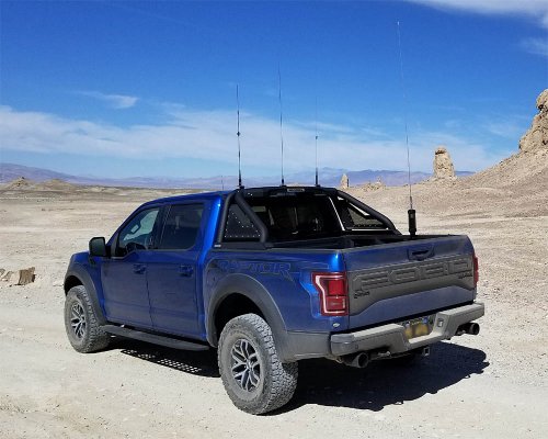
VHF/UHF antennas and scanner antenna will go on the light tray of the sport bar, which can be layed down electrically (using upfitter switches). The HF antenna will be mounted so the top of the coil is at roof top level, and the whip section can be removed. This allows everything to be stored lower than the tip of the stock AM/FM antenna if needed, such as for drive through or parking structures.

But in order to run all the wiring I will have to take the interior apart quite a bit. Remove A piller covers, lift up center console, get under carpet, etc. Is there a good resource with pictures or drawings showing these parts and how to remove / dismantle them?

Of course, it ain't rocket science, so it should not be hard, but it is always nice to know about that hidden clip before you start prying on a plastic panel.

Thanks,

T!
 

hammer73

Full Access Member
Joined
Apr 13, 2018
Posts
186
Reaction score
65
Location
Hillsboro, Oregon
Just about to start the same project. VHF/UHF first.

Definitely interested in any tips that help me feed cables from the mirror/sunglas/switches area to the center console / back seat.


Sent from my iPhone using Tapatalk
 
OP
OP
O

OriginalToken

Full Access Member
Joined
Apr 17, 2018
Posts
180
Reaction score
155
Ditto. Headliner also a plus. I'd also like any tips of bed exit/cab entry points.


For me I did not have to pull the headliner for anything. I pulled the overhead console, just pull on it, it is held only by clips, but pretty strong clips and a number of them, so it is pretty secure. Once I had that and the A pillar cover off (remove two bolts at either end of the A pillar hand grip, then pull off cover) I was able to use a stiff piece of wire as a snake, push the snake from the overhead opening to the top of the A pillar, and pull through the wires I needed in the overhead.


I did not need to pull the roof liner as I did not do roof mounts for any of the antennas. Rather, I mounted them on a sport bar with a powered light lay down shelf. This allows me to lay 3 of the antennas down, using Aux switches, for low overhead areas, parking garages, drive throughs, etc. The HF antenna is not yet on a power lay down, but that is in the works, for now I have to pull the whip off that by hand, but at least it has a quick disconnect. So it takes me seconds to get the truck in a configuration where the tallest part is the factory AM/FM antenna.

Truck_radios_01.jpg


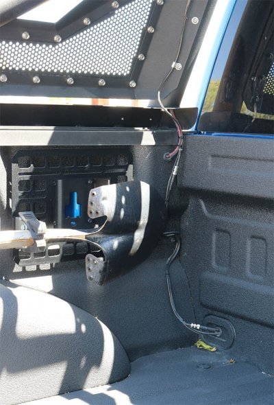
Bed exit points were several. At the top of the bed next to the front and rear rail pockets there is a pre-existing hole. I was able to grommet that hole and use as needed. I did have to enlarge one of the holes I used slightly to get the coax through I needed. Also, forward wall of the bed, lower right and left corners, is a large rubber plug. It can be popped right in and out. I used this (drilled the appropriate sized hole and grommeted) to route a couple pieces of coax out of the bed. However, there is some potential for this location to be pinched by gear in the bed, so it might not be right for everyone.


The picture below is of the sloppiest corner in my install, but it shows both of the routes I mentioned above. I have since covered the lower rubber plug area with a small shield / box to protect the wires from things laying in the bed sliding into them.

Truck_radios_05.jpg


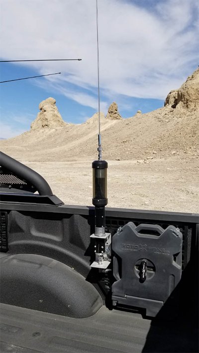
The back corner was much cleaner, near the upper right corner of the Builtright rack in the below picture there is an existing hole. I had to enlarge it slightly and put in a grommet. Then the coax and the control cable for the Tarheel 75A went right through.

Truck_radios_04.jpg


Cab entry points are also several, it just depends on what you want to do.


At the back of the cab I ran 4 coax’s and one antenna control cable into the cab from outside without cutting or drilling anything. Behind the rear seats (this is a SCREW, I assume a SCAB is similar), on the back cabin wall and behind the carpet, there is an air vent that allows the cab to burp air when you close the doors. Most vehicles have these of some kind so it is not painful on the ears when you slam a door while setting inside. I was able to route coax through these vents on the drivers side back wall. The grid on these are small squares, so some coax fittings may not fit, I found that Mini UHF (both male and female, female was the easier of the two) just fit, anything larger would not.


If you don’t want to do that there are several plastic and rubber plugs in the floor that could be drilled to allow passage. However, all of these I found put the coax under the carpet where peoples feet go or gear would be stacked, and I don’t really like that if I can avoid it. All of my coaxes are under carpet / behind panels, so out of sight, but not where people put their feet or any gear.


To get power in from under hood to cab was pretty easy. On both the drivers and passengers side firewall there is a large, 6”-ish, rubber boot around the factory cable bundles that go between cab and engine area. Offset from the existing bundle, molded into the rubber boot, is a half inch or so diameter rubber nipple on both (inside and outside) sides of the boot. I cut / punctured this nipple inside and outside, and used a piece of welding rod to guide / push the power line through the cuts.


T!
 
Last edited:

VLOCRPTR

Member
Joined
Sep 16, 2018
Posts
35
Reaction score
57
Location
Charlotte, NC
Thanks! I have the added complication of LineX (which I managed to chip off) AND a Decked system :) I went through the ammo cans in the front of the bed (nearest to the cab) like you show in the picture and now have to fish and find the best entry point into the cab itself based on some of the size limitations you mention.

I've got power to run on one side (2 guage for the secondary battery) and then antennae on the driver's side as well as the positive/negative cables back to the SwitchPro (which is in a "power pod" in the bed with the battery, etc.) vs the upfitter switches.

Thanks again. very useful.


Write your reply...
Top