OriginalToken
Full Access Member
- Joined
- Apr 17, 2018
- Posts
- 180
- Reaction score
- 155
There is a WAYYY easy way to do this. Simply use limit switches (Most likely built into your actuators) and a dual relay to reverse polarity.
This is how the electronics for our Motorized VHF antenna mount work....
This way, when you turn power on it goes up...power off it goes down.
I considered doing this myself, however I decided this was not the best fit for me.
In the above case the relay provides one polarity when the vehicle is turned on, and the opposite polarity when the vehicle shuts off. A time delay relay then disconnects voltage X seconds after the vehicle is shut down, after the antenna / light bar is driven down, to not drain the battery. Some designs may forgo the time delay relay and rely only on the actuator limit switches.
In such a case the antenna / light bar drives up as soon as you turn the ignition on, and turns off when you shut off the ignition. It does not require use of an AUX switch at all.
This was not applicable to my use, as I wanted to be able to drive the antennas selectably up or down anytime the switched accessory power is on.
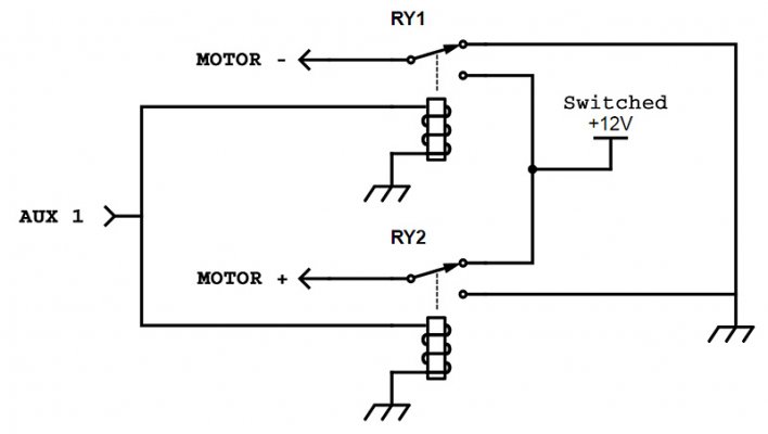
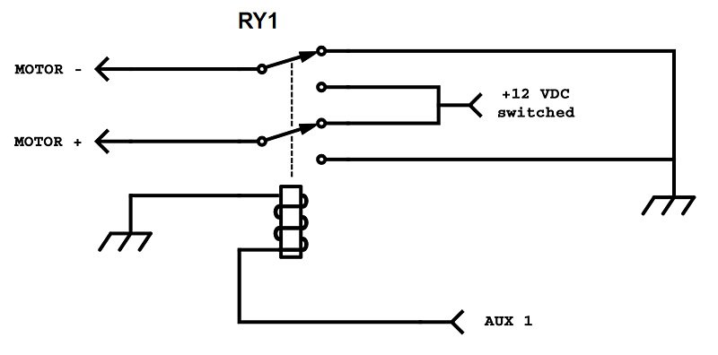
To do what is being described above, but using AUX switches instead of automatically happening on power on / power off, you still use a relay to reverse polarity, and you use one of the AUX switches, instead of ignition switched 12 VDC, to close the relay causing the polarity reversal.
It works like this, the relay is wired so that ignition switched power of one polarity (+12 VDC on red wire, ground on black wire) is always going to the antenna / light bar actuator. Lets say it is the polarity for driving the bar up. The bar drives up until the limit switches in the actuator stops the drive in the maximum up position. And there the bar stays. Power is still applied to the actuator as long as the ignition is on, however because of the limit switches the actuator is not trying to drive at all, it can be left in this condition indefinitely.
To drive the bar down when you want it down you close the relay, using voltage from an AUX switch, and the drive polarity reverses (now, compared to above, ground on red wire, +12 VDC on black wire). The bar will then drive down until the lower limit switches stop the actuator. Again, it will only drive to the limit switches and can be left in this condition indefinitely. It will stay in the down position as long as the AUX switch is left on.
This allows you to drive the light bar up and down using only a single AUX switch. AUX switch off and the light bar drives up to its maximum up position, AUX switch on and the light bar drives down.
Why did I not choose this route for my application and instead use two AUX switches, one for up and one for down? A couple of reasons. With the above you cannot stop the light bar in a partially raised position, it is either all the way up (hitting the up limit switch) or all the way down (hitting the down limit switch). Also, there is always voltage of one polarity or the other going to the actuator, even after the actuator has stopped moving. I would rather have the supply lines dead except when actually needed to drive the bar. Using the technique I did select (using two AUX switches) I can stop the light bar on any angle, and there is only drive voltage present while I have one of the AUX switches on.
Schematics below to do it with a single AUX switch used.
Using two SPDT relays:

Using a single DPDT relay:

T!
Last edited:

