G's Raptor

Disclaimer: Links on this page pointing to Amazon, eBay and other sites may include affiliate code. If you click them and make a purchase, we may earn a small commission.

OP
OP
E63

E63

Full Access Member
Joined
Feb 7, 2012
Posts
473
Reaction score
325
Location
Poway, CA.
Dash Z Replacement Headlights

I should note this was done a while ago, and Either the Ducatti were not yet released or I just never came across them in my searching...


Dash Z were not my first choice, but they seemed to be the most practical. I liked the Sick HIDs the best, but in order to get these bad boys you have to send him yours and then wait 6 weeks because this guy does some amazing custom work and he is popular. So who can keep their Raptor with no lights for that long? So you end up buying new ones to mod, cheap replacement ones to hold you over or try and find some used OEM at reasonable price.

These CCFL Dash Z's I opted for are the 55W 6000K Projector HIDs were $530 with on-line discount code. I had to wait 6 weeks for delivery. I have several buyers waiting for my stock lights at $350, so this mod (if I keep them) will not end up costing me much.

Here is the description from their site:
These 09-10 Ford F150 projector headlights come with the latest design twin CCFL halo angel eyes rings, and give your 09-10 Ford F150 an outstanding look. CCFL (Cold Cathode Fluorescent Light) is the latest technology in halo lights development, it gives 3 times light output than normal halo rings, but it is more durable, and it consumes less energy. CCFL also lights up faster in low temperature. The projector headlights are with OEM standard quality and are designed for stock lights direct replacement.

Fitment: 2009, 2010 ( 09, 10 ) Ford F150


So obviously they also fit 2011 and 2012

Above description explains what CCFL Halos are, but what do all the other options mean?

HID = High Intensity Discharge
Projector = means that they have a special lens assembly that magnifies focuses the beam along with providing a cutoff, so you can adjust the light to not blind on-coming drivers
55W = how powerful (Watts) the output is, standard is 35W
6000K = 6000 Kelvin = color / temperature of the light output

Here is a description of the color template choices
3000K is amber - think fog lights, also used in some applications for high dust
3000k.gif

4300K provides the greatest amount of usable light - plain White
4300k.gif

6000K Has the next highest available light, but has a high tech blue tint to it
6000k.gif

As you go up in Kelvin, additional choices are 8000K, 10,000K and the extreme 12000K shown below, The light becomes less usable and more blue/purple in color
12000k.gif

Installation

First remove the push pin by unscrewing or prying out center pin
DSC02246.jpg

Remove the top two 10 MM nuts - I circled in gold on the photo. I also point out where the Up/Down adjustment screw can be found.
DSC02247withtext.jpg

Remove the third 10mm bolt that was behind the rubber flap
DSC02248.jpg

It would be a good idea before removing light to mark a position away from a flat object and measure how high your current headlights project. I live at the bottom of a hill, so I pulled up onto a couple 4 x 4 and projected onto my garage door.

Here are some before pics:
DSC02252.jpg
DSC02250.jpg
DSC02251.jpg

Pull the light straight back, its a tight fit getting by hood stops. There are two locating pins and two clips that should stay attached to the lights.
Remove the two outer bulb connectors by turning a 1/4 turn counter-clockwise, the center one is released by pushing a tab on the connector while pulling.

The large amber side light gets put back into the new light the same way.
The small bulb from the other side is removed and the connector from the Dash Z plugs into its place. this is slipped inside the housing using the oem part of the harness to seal the light.

I had an issue with one of them, it was too loose and the halos would not stay on, so I carefully moved the wire pins to the side and put a small piece of shrink tubing, shrunk it down and re-installed the wire pins, now it fit nice and tight.

The middle connector simply plugs into the new housing.

Here is the back of the Dash z.
DSC02253.jpg

After Pics (before adjustments)

DSC02261.jpg
DSC02265.jpg
DSC02267.jpg

So the plan is to use them for a few days, maybe blast them with the pressure washer to make sure they stay water tight. I sincerely doubt they will leak, they look like they are well made and well sealed.

It is interesting in that they have locations for two more LEDs at the bottom of each light but none installed. By design? A mistake?

I only drove around a little, did stop to lower them driving up the street.
DSC02269.jpg

Its not like my MBZ, but its a 150% better than the stock POS lights. Now I know there are many who have dropped in HIDs into these stock lights and rave of the results, and this may be all true. But I do like the look of the CCFL Halo and a true projector lens.

I'll take some more pics of what she looks like in the daylight and post, but for now...
 
OP
OP
E63

E63

Full Access Member
Joined
Feb 7, 2012
Posts
473
Reaction score
325
Location
Poway, CA.
Dash Z Lighting Part 2

Called up the Mfg. Turns out my order was incomplete. HID is coming as a kit separately from Fedex. Not to happy about the poor communication as I expected the unit to ship complete and pre-installed.

Instant Gratification - thats what I wanted.

Here is an HID Installation video that dash links to:
Install HID Conversion Kit - YouTube

Turns out what I have on the unit so far is an H7 in the "Halogen" style projector. So I should see a huge improvement over what I have now. The good news is that the cut-offs are very sharp, just needs more HP.

Oh, Matt, I did find out that these specific ones are made for Dash Z by CG Mfg. They claim no relation to Recons or Spyders. Also open two spaces that look like they were designed for LEDs are empty by design.

Here are some pics from this morning and (Abby's 8th Grade Promotion)

DSC02290.jpg
DSC02292.jpg

Dash Z Headlights - Part 3 – HID Kit Install – Post 1
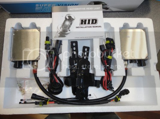
Got the package yesterday, waited till 4:00 in afternoon and ripped into it at work.

DSC02330.jpg
DSC02329.jpg
DSC02332.jpg
DSC02333.jpg
DSC02334.jpg
Looking at the wiring, I was confused at first how it was going to work with the raw connections on the inside of the seal.

Removed headlight, as I found out, the connections and the bulb locations are completely separate. All the wiring connections are inside the housing. Large rubber caps seal both the projector low beams and the Halogen High Beams.

The instructions alone are almost worth the cost of the kit. The transliterations are very funny. “be careful to not mis-connect reversedly”.

Unfortunately they are for multiple types of installations, some of which require separate relays. The H-7 kit does not and also does not require any direct connections to battery or ground.

The wiring is very straight forward.
Remove cap over the projector low beams, undo wire hold clip, remove H-7 bulb and remove connector from back of bulb. Be careful to not touch glass on this or new one, set aside old bulb. Remove wire connector from old harness by inserting flat blade screwdriver to release clip on brass connector as pictured.
DSC02337.jpg
DSC02339.jpg

I found some extra strands on the oem harness needed to be cleaned up. I wrapped in some electrical tape on the sharp side and slipped some shrink tubing over the connectors before connecting to new harness. Black to black, Blue to Red. Made the connections, shrunk the tubing.
DSC02344.jpg
DSC02345.jpg

Next step is to cut 25 mm round hole in back of rubber cap. I used the packing washer from the new bulb as a template, it was pretty close at 27 mm, so I drew thick black line using sharpie and cut to inside (smaller) with razor blade (no exacto knife at work.)
DSC02341.jpg
DSC02342.jpg
DSC02343.jpg

As you can see I hacked it up pretty good, but it works fine and irregular cuts are completely hidden under rubber grommet. Re-install cap, I moved inside wires to side so nothing is pressing on inside of grommet.

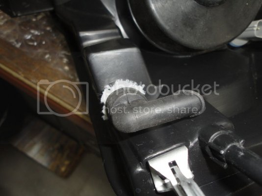
Note: While it was on the bench, I had a good opportunity to examine construction in good detail. The lights themselves are well sealed, sticky "flowed silicone" is abundant around entire perimeter seal, all connections are watertight and are designed to be fairly idiot proof. I did notice a vent cover that I believe is for evaporation of any water vapor and heat expansion/ breathing, the angled rubber breathing tube protects against water back splashing.
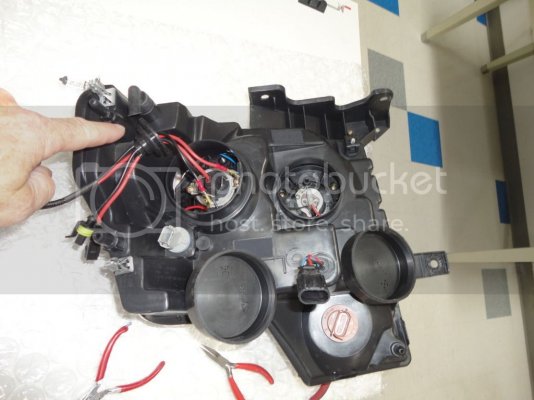
DSC02340.jpg
I believe it would need to be submerged for some time for water to penetrate.

I do have concerns about dust getting thru this opening and decided to add a cloth filter.
DSC02346.jpg
DSC02347.jpg
The first one I simply slipped the cloth between the rubber and plastic, the second one I zipped tied down as it seemed like it might vibrate off. After sleeping on it, I am going to remove both lights again and try and come up with a more effective dust shield. I am now thinking that dust will simply go thru a single layer of cloth. I am also going to JB weld the metal side clips on one unit as they will no longer stay in place (Installation boo boo)

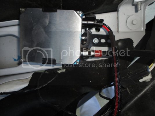
Before installing the light housings, I decided to install the Ballasts to the cross frame member. A couple of self taping metal crews made for short work. The right side needed to be angled due to rubber shield connected there. DSC02348.jpg
DSC02349.jpg
Connected ballasts to housing, installed ballast into bracket, reconnected oem harness – 3 connections, tested and then bolted back in.
Repeated for other side.

Installation complications:
I had issue on turn signal oem connector, would not release at connector so I simply remove entire bulb with connector on that one, no big deal.
Bent a pin on the parking light connector, same one that I had trouble with in Part 1, fixed the bent pin, but then it didn’t work, had to remove and redo that pos connector that I had used some shrink tubing on, must have pulled it loose while fixing the bent pin, anyway, it is fixed and working well.

Tried to take some of the same set up pictures as I did on the first install. Due to late hour, I tried to do without tri-pod, wrong, 1 second exposure hand held = blurry pictures.
Then camera battery died, so sorry, only a couple pics worthy of showing.
DSC02351.jpg
DSC02354.jpg
DSC02350.jpg

Impressions so far:
I really like the lights, both the looks and performance. HID installation was a lot simpler than others. Instructions sucked other than the humor factor, but you have mine above so don’t let that effect your decision. Price is right. Cutoff is outstanding. There is a small gap in the middle where the two light streams do not connect which is odd. They need to improve the parking light connector to the oem harness. It would be nice if they provided dust filter for vent tube.

Finally, I would love to find a way to have “Daytime Running Lights”, I saw when researching that some believed the dealer could program (did I ever mention how much I loath taking my vehicle to a dealer?), I am also going to ask Mike at 5 Star.
 
OP
OP
E63

E63

Full Access Member
Joined
Feb 7, 2012
Posts
473
Reaction score
325
Location
Poway, CA.
RPG Race line Upper Control Arms

DSC02370.jpg
As most of you who have been following my thread know that I am relatively new to this sport and have never built or modified the suspension of an off road vehicle before so it has been the forum’s members and vendors along with the internet where my knowledge comes. Continuing this thought pattern, I found a great fit with RPG, I really liked how all of their components were designed to work with each other and could be added incrementally. I didn’t know I was going to get bit by the mod bug, but infected I am. As I lust for more and more performance, RPG has been there to feed my habit and I truly enjoy their friendship and free sharing of their considerable experience and time.

Yesterday was another in a series of days where work was performed together, what was different is that we decided to go play afterwards. Ok... I'm game. But first let me do the write ups.

First the UCA’s , later will post the rear Springs and some videos of our testing.

Here is the pitch from RPG’s site:
Raptor Performance Groups Upper Control arms carry over the same design and build quality that you see on modern day race trucks. They are crafted from a 3D Cad design that ends up being CNC laser cut and folded for a precision fit and finish. RPG UCA’s are designed with the future in mind. Unlike other aftermarket control arms available on the market, we dramatically changed the bearing cup angle of the arm to ensure proper geometry to enable the use of aftermarket Coil Over shocks which allows for greater amounts of droop travel. When others UCA’s will bind metal on metal, your RPG unit will allow for a full range of wheel travel without any damaging affects down the road because of the aggressive cup angles used. This also remains important when moving your OE Raptor shock to the 2nd or 3rd perch setting.

On many of our competitors UCA’s you will also find ½” bolts holding the arm to the spindle or at best a 4340 heat treated center pin. When you opt to go with a Raptor Performance Group UCA Race Line, you will find our center pins are 5/8th 300M material which is 5X’s stronger than a grade 8 ½” bolt, and 2X’s stronger than a 4340 heat treated pin. Our center pins are black oxide coated to help prevent rust and corrosion. If there is one thing we have learned over the years in Baja, it’s don’t gamble with lesser materials.

The third major benefit of choosing a Raptor Performance Group UCA Race Line version is the ease of installation and maintenance on the chassis pivot points. While others use ¾ Heims, we opted to go with 1.0” stainless steel spherical bearings with stainless steel mis-alignments for exact fit and much greater strength. Using fixed spherical bearings eliminates the head ache of trying to nail down a proper alignment and guarantees our arms drop right into place of the old OE Ford UCA.

These arms are perfect hardcore off-roader who is looking to get the most out of their setup. You will gain Strength, Longevity and Flexibility for future suspension upgrades to take your current set-up from mild, to wild…

• 300M 5/8” Center Pins
• 3D CAD Design
• Outer 1.50” FK spherical bearing with Teflon liner
• Aggressive cup angle allowing for more drrop travel without binding
• 1.00” spherical bearings vs. Heim joints
• CNC Laser cut and folded box design for greater strength
• Titanium Powder Coat Finish
• An Alignment is not necessary but is recommended

Installation:
Remove tire, Shock, Brake line bracket, Tie rod (from Clevis end). Install Knuckle pin – process is almost identical to the Tie Rod installation documented earlier in this thread. All torque values to mfg. OEM spec. (UCA Chassis side 125Lbs, Knuckle Pin 80Lbs top, 100Lbs bottom)

The one difference is that the Knuckle pin was maximized in size for additional strength and it requires a little filing in order for it to push through far enough for the bottom threads to come through. Either use a file or a 5/8” drill bit.

DSC02368.jpg
DSC02373.jpg
DSC02372.jpg
DSC02374.jpg
DSC02375.jpg
DSC02377.jpg
DSC02382.jpg
DSC02394.jpg

The clearance between the coil over and the UCA at full droop just kisses the side of the coil. If it was of concern, we could compress the coil and spin a little so it misses. The other side misses.

DSC02385.jpg
DSC02384.jpg
DSC02371.jpg

While we had everything apart, I asked if we could document the extra droop travel of the new shocks and UCA. To do this we needed to reinstall one of the old 2.5 fox shocks. We measured from the inner fender liner to center of wheel hub. As you can see, this increased droop from 29.25” to 29.75” so about ½” by this measurement. Fox later confirmed the increase in travel is 5/8" so we were pretty close!

DSC02388.jpg
DSC02387.jpg
DSC02392.jpg

The odd thing is that in order to reinstall the tires, we needed to significantly increase the jack height from where we took them off. The first tire, we thought maybe something got changed so we were watching for it on the second. We needed to jack up the side about 2” more to mount the tire after the new UCA’s were installed.
We also raised the front by increasing the front coil spring “pre-load”. We did 5 turns of the collar to the left spring and 4 on the right. Since the shocks were off the truck we did on a cart, but could have easily done this while on the truck. Picture shows the Milwaukee 18V but sadly these springs were its match, out came the pneumatic wrench.


Performance:

Noticeable difference in performance from the front end with it being raised and the full travel of the Fox 3.0. Only negative, and this is minor, is that the large nubs on the outside of my 37" KM2 rub slightly at full lock and only notice it in reverse. It doesn't make a noise like the fender liners did when they rubbed - that was an ear offending nail on chalkboard screech. This rubbing is only felt as a oscillating vibration.
 
OP
OP
E63

E63

Full Access Member
Joined
Feb 7, 2012
Posts
473
Reaction score
325
Location
Poway, CA.
Did RPG change the raceline upper control arm bolts.. Mine looks different than yours..

View attachment 9675

-Greg

Hard to tell from your picture. I should have mentioned that RPG offers their Raceline seriies of UCAs in both a 1.5" and 1" outer bearing. Since I use the stock wheels I had to go with the 1".

I believe we used the stock bolts - all the new stuff is pictured in the first pic of the post.

How do you like yours?
 

Squatting Dog

FRF Addict
Joined
Jun 1, 2011
Posts
8,602
Reaction score
4,103
Location
Kansas City, MO
That is the difference... Mine are 1.5 raceline. It is amazing change on the feel/control of the truck. Make the 3 ton beast feel like an YZ50...

-Greg
 

RangerRob

Full Access Member
Joined
Jun 6, 2012
Posts
358
Reaction score
271
Location
Ramona, CA
Your truck is badass Man. I'm hoping to get all RPG's parts on my truck soon. Then We'll be the two RPG'd Raptors running around Poway.
 

KaiserM715

Kaiser Söze
Joined
Aug 5, 2010
Posts
8,571
Reaction score
3,118
Location
Houston, TX
While we had everything apart, I asked if we could document the extra droop travel of the new shocks and UCA. To do this we needed to reinstall one of the old 2.5 fox shocks. We measured from the inner fender liner to center of wheel hub. As you can see, this increased droop from 29.25” to 29.75” so about ½” by this measurement. Fox later confirmed the increase in travel is 5/8" so we were pretty close!

This is good info and the first time I have seen it. Thanks for getting it!!
 
Top