2013 Vehicle Alarm Wiring Questions.

Disclaimer: Links on this page pointing to Amazon, eBay and other sites may include affiliate code. If you click them and make a purchase, we may earn a small commission.

peepsnet

Full Access Member
Joined
Jan 27, 2014
Posts
52
Reaction score
14
Location
South Florida
Hi All,

I purchased a GPS Tracker/Alarm System for my 2013 SCREW.

I am looking for help on wiring this up. I have not received the thing yet(shipped from china) but I am trying to plan my installation.

I cannot find an online manual for the GPS107 but I found a wiring diagram. I'll hopefully have more info when I get the alarm.

I know that there are not too many specifics about the wiring but I would like to know a few things.

Can someone explain the "possible" meaning of:
(+) Door Trigger
(+) FootBrake Trigger
Am I looking for a connection that would be made hot when activated? Like the dome light or brakelight

I guess this is a grounded connection, like to a N.O. pin switch(or a pin switch that is grounded(closed) when depressed):
(-) Door Trigger
(-) GripBrake Trigger
(-) Bonnet Trigger


First:
How would I wire this thing to be able to cut the engine. I don't think turning off the oil pump is the best way. Assuming I could use a N.O. or N.C. relay how should I wire this???

Second:
Where would I need to hook up the ACC wire?

Third:
Which "Door Trigger"... The positive(+) or Negative(-) and where would I hook it up?

And Lastly:
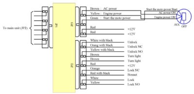
I would like to be able to use the remote lock system so I can lock the truck remotely by SMS also. I have attached the "central locking system" diagram below as well.

I'll accept the fact that there is not enough information to give the perfect answer but again... I am just looking for planning.

Thanks to all who respond!!
Don

922337972_780.jpg


centrallockingdiagram1.jpg
 

badmonkey

Full Access Member
Joined
Jan 4, 2014
Posts
166
Reaction score
41
Location
Western Suburbs of Chicago
The positive and negative trigger is referring to the type of system the vehicle uses. For example, when you press the lock button, is a positive signal sent to the actuator, or negative (ground). I don't know which system we have, I'm sure a quick google search will tell you.

---------- Post added at 09:05 PM ---------- Previous post was at 09:02 PM ----------

The ACC signal is any switched 12v signal, when the key is in the accessory position.

---------- Post added at 09:08 PM ---------- Previous post was at 09:05 PM ----------

Honestly, I'd get a professional to do this job, there are many variables with today's vehicles (transponder keys), that might interfere with this system. I'm new to the Fords, but I do have electronic experience.
 

The Car Stereo Company

aka grumpy car stereo guy and frf rolodex
Supporting Member
Joined
Jul 8, 2012
Posts
32,533
Reaction score
23,498
Location
here, on frf
i am heading home right now, but i will try to answer all your questions tonight so you can experiment tomorrow morning.
 
OP
OP
peepsnet

peepsnet

Full Access Member
Joined
Jan 27, 2014
Posts
52
Reaction score
14
Location
South Florida
The positive and negative trigger is referring to the type of system the vehicle uses. For example, when you press the lock button, is a positive signal sent to the actuator, or negative (ground). I don't know which system we have, I'm sure a quick google search will tell you.

I'll try. GIYF

Found a reference in a Viper manual about Fords being mostly Positive trigger but I'll check with a meter when the time comes

The ACC signal is any switched 12v signal, when the key is in the accessory position.

Is there a preferred/better something to use

Honestly, I'd get a professional to do this job, there are many variables with today's vehicles (transponder keys), that might interfere with this system. I'm new to the Fords, but I do have electronic experience.

I am not looking to bypass many of the factory alarm parts. At the most I want to lock the doors and kill the engine

I am familiar with electronics also but have no idea about the wiring on this beast. Is there a diagram for the F150 Raptor with locations of the harnesses?

Got a friend that does custom car audio and alarms so hopefully the 2 of us can get somewhere.

Don

---------- Post added at 10:50 PM ---------- Previous post was at 10:43 PM ----------

i am heading home right now, but i will try to answer all your questions tonight so you can experiment tomorrow morning.


Your a lifesaver!

I used your Dash Video to tear apart my dash and get started on some wiring(hopefully I will be able to write up a good piece on the whole project once complete)

Thanks,
Don
 
Last edited:

The Car Stereo Company

aka grumpy car stereo guy and frf rolodex
Supporting Member
Joined
Jul 8, 2012
Posts
32,533
Reaction score
23,498
Location
here, on frf
Hi All,

I purchased a GPS Tracker/Alarm System for my 2013 SCREW.

I am looking for help on wiring this up. I have not received the thing yet(shipped from china) but I am trying to plan my installation.

I cannot find an online manual for the GPS107 but I found a wiring diagram. I'll hopefully have more info when I get the alarm.

I know that there are not too many specifics about the wiring but I would like to know a few things.

Can someone explain the "possible" meaning of:
(+) Door Trigger

a positive door trigger is a system where when the door is opened, it will complete the circuit sending power to the bcm
(+) FootBrake Trigger

this is the wire that shows 12 volts when the foot brake is depressed and shows nothing (or ground) when the brake is released
Am I looking for a connection that would be made hot when activated? Like the dome light or brakelight

I guess this is a grounded connection, like to a N.O. pin switch(or a pin switch that is grounded(closed) when depressed):
(-) Door Trigger
(-) GripBrake Trigger
(-) Bonnet Trigger


First:
How would I wire this thing to be able to cut the engine. I don't think turning off the oil pump is the best way. Assuming I could use a N.O. or N.C. relay how should I wire this???

most alarm systems have a starter kill. this is a relay inline preventing the vehicle from starting when the alarm is active. the relay is usually activated with a "ground when armed" wire from the aftermarket alarm
Second:
Where would I need to hook up the ACC wire?

accessory can be found in the ignition harness. it is a purple/green wire
Third:
Which "Door Trigger"... The positive(+) or Negative(-) and where would I hook it up?

the door trigger on these trucks is a negative trigger. and each door is pinned seperately. this means you must find each door wire an diode isolate to keep from signal backfeeding. the only positive door trigger is the dome supervision wire. the issue with this wire is that on some vehicles it will not send signal if the dome light is set to off.

And Lastly:
I would like to be able to use the remote lock system so I can lock the truck remotely by SMS also. I have attached the "central locking system" diagram below as well.

you will need to find the lock and unlock wires in the vehicle. there are the motor wires and then there are the signal wires. the motor wires go directly to the door locks and is a 5 wire reverse polarity setup. the signal wires send a negative signal to the bcm which tells the bcm to lock all the doors. these are the wires you will need.
I'll accept the fact that there is not enough information to give the perfect answer but again... I am just looking for planning.

Thanks to all who respond!!
Don

there is a module called the dball and the dball2. these are specific to directed products (viper, clifford, avital, rattler, python, etc...) this module can also work in whats call wire to wire mode. this will allow you to connect to the system through the canbus system which can control the door locks, door triggers, and is necessary when adding remote start. the key to the truck contains a microchip and the dball(2) learns the key code to allow for remote start when the key is not present. this does take both keys to program, but it is the only way to program remote start. unless you use a module like the 556u which requires you put a key in the module and bury it in the dash. this is not a simple project and will take quite a bit of time to complete. be prepared to have your truck apart for quite some time.
922337972_780.jpg


centrallockingdiagram1.jpg

here you go.
 
Last edited:
OP
OP
peepsnet

peepsnet

Full Access Member
Joined
Jan 27, 2014
Posts
52
Reaction score
14
Location
South Florida
Help me Obi-Wan Kenobi, Your my only hope!

NOAH!!!!!!!! Just a moment of your time please!!!

Help me Obi-Wan Kenobi, Your my only hope!

got about half wired up.

Got:
Power
ACC
GPS nounted
Cell antenna mounted
Shock sensor
Siren
Speaker & Mics
Alarm LED
Panic button

Still need:
Dome light
Door locks
Blinkers
Hood pin switch
Tailgate pin switch(boot)

I am trying to keep all as much of the connections on the passenger side kick panel as possible so I would like to start there.

I still need some help getting the wiring for a few of the things.
I need to know where one would connect the Door Trigger. I am assuming we could use the dome light for that.

Where is the dome light wire?

Where are the blinker wires(other then immediately behind the blinkers)??
Hoping for somewhere in the cab if its not impossible to get to.

And the door locks... I have attached the Wiring of the "Central Locking" thing. I am not going to use the remote start so ignore JP3
you will need to find the lock and unlock wires in the vehicle. there are the motor wires and then there are the signal wires. the motor wires go directly to the door locks and is a 5 wire reverse polarity setup. the signal wires send a negative signal to the bcm which tells the bcm to lock all the doors. these are the wires you will need.
Where are these wires??
How would I hook this up??


Thanks
Don
 

Attachments

  • 1380440975.jpg
    1380440975.jpg
    35.4 KB · Views: 598

BAJASVT

FRF Addict
Joined
Nov 7, 2011
Posts
1,029
Reaction score
475
Location
SE Michigan
peepsnet - I don't have time to go through all the wires and/or circuits you're requesting, but if you send me your email address I can email you the wiring diagrams for all the BCM connectors.
 
Top