V-1 Radar Detector

Disclaimer: Links on this page pointing to Amazon, eBay and other sites may include affiliate code. If you click them and make a purchase, we may earn a small commission.

Raptor enroute

Full Access Member
Joined
Mar 4, 2010
Posts
202
Reaction score
2
I know on the other site there was a thread that explained this in great detail but like most I can no longer retrieve that information. So can anyone please identify the pins on the rearview mirror that are to be used for the installaion of the V-1 with invisicord. I have the navi system so the rear view cam will be displayed in the console vice the mirror. Appreciate the help.

Curtis
 

MagicMtnDan

FRF Addict
Joined
Oct 28, 2011
Posts
7,661
Reaction score
1,795
Location
Magic Mountain
I can do that. I was involved in the thread on the other forum. Unfortunately I didn't make a copy of what I wrote (whodathunk it would have been necessary?!) so I'll have to re-create it as best I can. Note that Mark T and at least one other person provided information relating to the harnesses and the pin locations so credit and thanks must go to them.

There are two different connectors and harnesses made for the Raptor. One is for the Raptors with the backup camera - it has 16 wires in it - and one is for Raptors with SYNC and that one has 10 wires in it.

Pin 1 on both mirrors is switched 12v. The wire color is Blue with red stripe. The power to this pin stays on like the radio does until you open the door or wait ten minutes.

Pin 3 is ground on the 16 pin mirror and the color of that wire is Black with a purple stripe.

Pin 10 on the 10 pin mirror is the ground and the color is also Black with a purple (violet) stripe

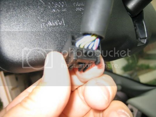
With the plug disconnected and hanging down from the mirror, sitting in the truck looking forward at the holes in the "white" end that plugs into the back of the mirror with the clip on the bottom side: Pin 1 is on the far lower left onand Pin 3 is on the lower row 3rd hole from the left.

If you are holding the 10 pin harness in your hand looking at the holes with the clip at the bottom then the 12v is at the bottom left and the ground is at the top right. The colors were exactly as posted. Also, on the back of the harness it is labeled 1 and 10.

It's small but I saw it while looking at the colors of the wires. To get the harness out you push up on the bottom of the clip and wiggle it back and forth.

The yellow invisicord wire goes in pin1 on the back and the black wire goes in pin 10.

Note: I will come back to this thread when I have time and update and add information.
 

MagicMtnDan

FRF Addict
Joined
Oct 28, 2011
Posts
7,661
Reaction score
1,795
Location
Magic Mountain
Here are the pics I took when doing mine:

IMG_1558.jpg

IMG_1561.jpg

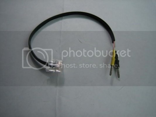
Invisicord:

IMG_1575.jpg

From Invisicord's website:

Do you have a mirror that has switched power supplied to it for features like auto-dimming, map lights, compass/temperature, or On-Star? If so, my cord may just be the solution for you!

If your mirror has these features, chances are the mirror has a wiring harness connected into the back of the mirror housing. My little contraption allows you to quickly connect my power cord right into the harness without any splicing or cutting any wires! You simply push the connectors into the back of the wiring harness to tap in to the proper +12v/ground wires. It is basically a 1 minute install!!!

Invisicord website: www.invisicord.com

IMG_1579.jpg

If you look closely on your connector you will see numbers on the wire locations (you may need a magnifying glass for that).

These pictures are of my Raptor installation and I have the 10 pin harness (with SYNC).

Pin 1 on both mirrors is switched 12v. The wire color is Blue with red stripe. The power to this pin stays on like the radio does until you open the door or wait ten minutes.

Pin 10 on the 10 pin mirror is the ground and the color is also Black with a purple (violet) stripe

IMG_1582.jpg

The Invisicord pins need to be forced in and they don't 'snap' or 'pop' into place. You just push them in about as far as they'll go and that's it.

IMG_1587.jpg

I used the Great Lakes Mount to hold my Valentine One (V1) radar/laser detector (more on that another time) and you see it in the pics above and below.

IMG_1586.jpg

Invisicords are available in different standard lengths ( 8", 12", 16", 20" or 24") and you can also have them custom made. I went with the shortest one - 8" and there is still extra length on my installation. The Invisicord wiorks with other radar detectors - visit their website for more info.

Let me know if you have any questions - feel free to PM me and I'll help you if I can.

Good luck!
 

Xjrguy

FRF Addict
Joined
Aug 8, 2010
Posts
1,331
Reaction score
12
Check out the Blendmount too if you want another choice in mirror mounts for radar detectors.

It works with the Ford mirror no problem.

If anyone wants pics, I can post them up of how it looks installed.
 

MagicMtnDan

FRF Addict
Joined
Oct 28, 2011
Posts
7,661
Reaction score
1,795
Location
Magic Mountain
Check out the Blendmount too if you want another choice in mirror mounts for radar detectors.

It works with the Ford mirror no problem.

If anyone wants pics, I can post them up of how it looks installed.


Hey LightGuy, please post your pics and info when you have a chance. This forum will keep the pics and info up unlike the other forum where they live to delete :D
 

MagicMtnDan

FRF Addict
Joined
Oct 28, 2011
Posts
7,661
Reaction score
1,795
Location
Magic Mountain
OK, at the risk of posting some redundant info and pics, I found the write-up I did previously (for some reason I was smart enough to save it as a Word document - in the future I should do that for all of the detailed posts) and here it is:

Valentine One (V1) Installed

As mentioned previously in my “Electrical Phobia” thread http://www.raptorforumz.com/showthread.php?t=1309&highlight=valentine, I was determined to install my Valentine One radar (and laser) detector in my Raptor using two cool products:

1. The Great Lakes Trophies and Engraving mirror mount originally designed for the C6 Corvette;

Current price: $32.00

Links:
http://69.89.25.185/~trexsoft/t-rexsoftware.com/greatlakes/corvette.htm
http://69.89.25.185/~trexsoft/t-rexsoftware.com/greatlakes/pdfs.htm
http://69.89.25.185/~trexsoft/t-rexsoftware.com/greatlakes/pdfs/V1C6MirrorMount.pdf

Here is the Great Lakes bracket:
http://69.89.25.185/~trexsoft/t-rexsoftware.com/greatlakes/images/v1c6mirrormount.jpg[/IMG}

2. The Invisicord Products wire (6” long version) designed for a stealthy installation of Valentine One and the Passport radar detectors.

Here is the Invisicord wire as delivered:
[ATTACH=full]178331[/ATTACH]

The Great Lakes mount had to be modified because the back of the Raptor mirror is different from the back of the C6 mirror (the Raptor’s snap-in wiring plug is located nearly in the center of the back of the mirror).

Here’s the Great Lakes bracket (with 3M adhesive) and the visor bracket that comes with the V1 detector (shown with the visor clip removed). The visor bracket clips onto the Great Lakes bracket and holds the V1 unit.

Picture of the Great Lakes bracket with the V1 Visor bracket together:
[ATTACH=full]178332[/ATTACH]

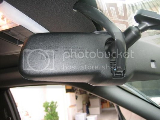
Back of the Raptor mirror as seen from the passenger’s seat:
[ATTACH=full]178333[/ATTACH]

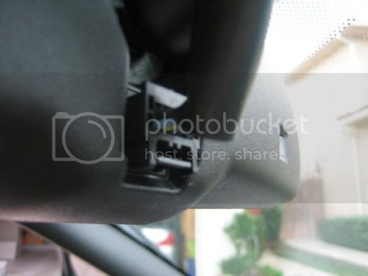
Close-up of the 10-wire connector on the back of the Raptor mirror. Note: The 10-wire connector is used on the Raptors with the SYNC system. The 16-wire connector is used on Raptors with the mirror display:
[ATTACH=full]178334[/ATTACH]

Another pic of the assembled brackets:
[ATTACH=full]178335[/ATTACH]

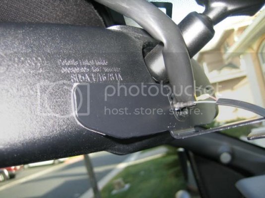
Here you can see the Great Lakes bracket below the Raptor mirror. Note the female snap connector location and how the bracket will cover it:
[ATTACH=full]178336[/ATTACH]

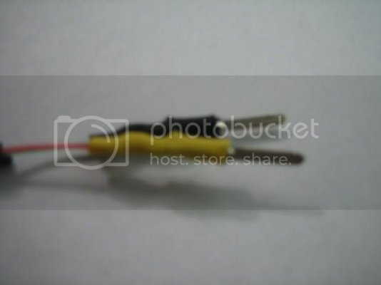
Here are the connectors that are pressed into the sockets for the (1) switched power and (2) the ground wire:
[ATTACH=full]178337[/ATTACH]

When you remove the snap connector from the mirror you will see (if you put on your glasses) very small numbers on some of the pin locations.

Pin 1 on both mirrors is switched 12v. The color of this wire is blue with red stripe. On the Raptor the power to this pin stays on just like the radio does until you open the door or wait ten minutes. Pin 3 is ground on the 16-pin mirror. That wire’s color is black with purple stripe. Pin 10 on the 10-pin mirror is the ground. (Special thanks to forum member MarkT for this information!).

Not sure if you can see the numbers on the connector in this pic:
[ATTACH=full]178338[/ATTACH]

So I had to modify the Great Lakes bracket. I don’t have tools for metalworking (I’m a woodworking hobbyist) so I drilled a 1/2” hole in the center of the bracket. I used some heavy duty wire cutters to trim the excess metal (the bracket is painted steel – a good thickness). I used a file to deburr the edges and smooth the hole and cuts:
[ATTACH=full]178339[/ATTACH]

I pressed the yellow lead of the Invisicord wire into the Pin-1 socket. And I pressed the black lead of the Invisicord into the Pin-10 socket. I peeled off the double-sided tape protection and put the bracket in place and pressed it hard holding steady pressure to ensure it was securely in place. The double-sided tape is supposed to be good up to about 300F so it will hold the bracket and V1 securely in place:
[ATTACH=full]178340[/ATTACH]

Here you can see the blue switched power wire (lower right of the 10-pin connector). The ground wire is on the upper left on the 10-pin connector):
[ATTACH=full]178341[/ATTACH]

Here you can see forum member Microbomb’s pic of his Invisicord leads inserted into the snap clip on the back of the mirror:
[IMG]http://gallery.me.com/toddpike/100072/DSC_0166/web.jpg?ver=12612001880001

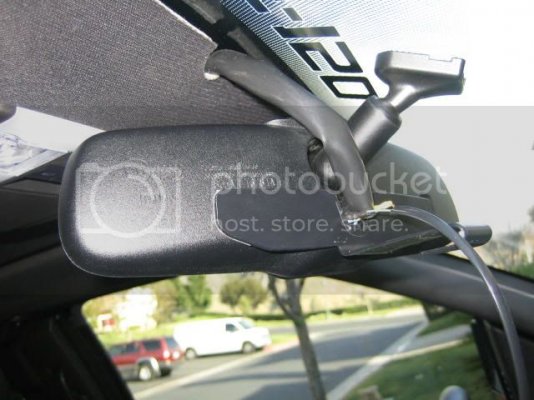
Here you can see the Valentine One (“V1”) held in place by the V1 visor bracket which is held by the Great Lakes bracket:
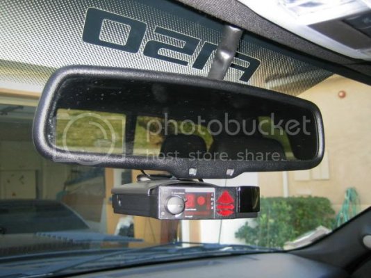
IMG_1589.jpg

It’s a very clean installation with no extraneous wiring or clutter:
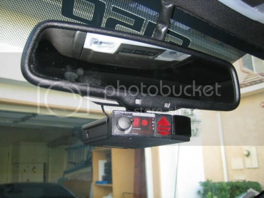
IMG_1590.jpg

The V1 unit has clear, unobstructed view ahead and to the rear offering me notification when radar and/or laser are being used:
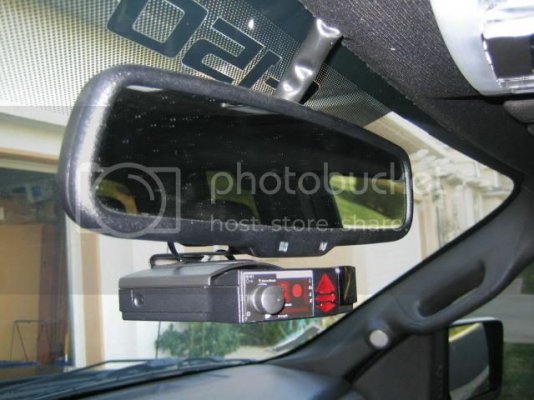
IMG_1596.jpg

Special thanks to forum members Microbomb and MarkT for their invaluable help. They identified the socket numbers for the switched power and the ground on both socket types (10-pin and 16-pin) and Microbomb installed the Invisicord in his Raptor with a Blend Mount and radar detector. You could have seen the original thread here but I understand it's been deleted: http://www.raptorforumz.com/showthread.php?t=1309&highlight=valentine
 

MarkT

FRF Addict
Joined
Mar 4, 2010
Posts
1,202
Reaction score
26
Like Dan, I never expected to have to save the info I posted on the "other" forums... but I did just find the notes for the pins:

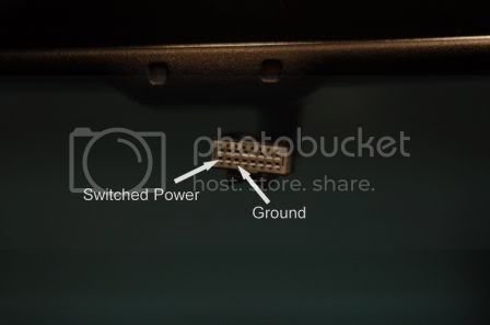
For the 16 pin mirror (backup cam without Nav)

Pin 1 = power
Pin 3 = ground

Here's the pic for the 16 pin mirror.

Mirrorpower16pin.jpg

For the 10 pin mirror (No backup cam or Nav with backup cam)

Pin 1 = power
Pin 10 = ground
 

MagicMtnDan

FRF Addict
Joined
Oct 28, 2011
Posts
7,661
Reaction score
1,795
Location
Magic Mountain
Update: 2010-04-20

Reason: 2010 6.2 Raptor without rear back-up camera has a 7 pin connector on the rear view mirror.

Per FSM06:

Pin Circuit Gauge Circuit Function Qualifier
1 CBP41 (BU-RD) 18 FUSE - 41 OR CIRCUIT BREAKER
2 CET47 (BU) 22 REVERSE LAMP RELAY COIL +
3 GD147 (BK-VT) 22 GROUND - PILLAR C LEFT
4 LRD12 (BU-OG) 22 CTRL MOD. - ELECTROCHROMIC MIRROR
5 RRD12 (BN-WH) 22 CTRL MOD. - ELECTROCHROMIC MIRROR
6 VMC31 (GY-BU) 22 COMPASS MOD. # +
7 VMC30 (BU-GY) 22 COMPASS MOD. # -

This should help GTS. Looks like pin 3 Black and Violet is your ground and pin 1 Blue and Red is your power circuit.

Link: http://www.svtoffroad.com/showthread.php?869-Wiring-invisa-cord-to-rear-view-mirror-(need-help)

Thanks to all for your continued information
 

Madcowranch

Genetically Modified
Joined
Sep 16, 2010
Posts
7,303
Reaction score
5,168
Location
OK
Need a little help here. Back of my mirror only has 5 wires! WTF? How many different connectors does Ford use?

I got Blue, (2) Blue/Red, Brn/Wht, and either a dark purple or black.
 
Top