Pass Thru Wires / Upfitter Switches Explained (Video)

Disclaimer: Links on this page pointing to Amazon, eBay and other sites may include affiliate code. If you click them and make a purchase, we may earn a small commission.

MarkT

FRF Addict
Joined
Mar 4, 2010
Posts
1,202
Reaction score
26
Nice video! I could have used this the other day when I was wiring up my lights! :thumbsup::thumbsup::thumbsup:

(I didn't remove the whole glove box door but I did figure out pulling the side panel next to the door really helps!)
 

IRONMAN2

Full Access Member
Joined
Apr 1, 2011
Posts
58
Reaction score
0
Glad you guys like it.
People were having a hard time so I decided to make this video to help out
 

IRONMAN2

Full Access Member
Joined
Apr 1, 2011
Posts
58
Reaction score
0
Glad you guys like it.
People were having a hard time so I decided to make this video to help out
 

MagicMtnDan

FRF Addict
Joined
Oct 28, 2011
Posts
7,661
Reaction score
1,795
Location
Magic Mountain
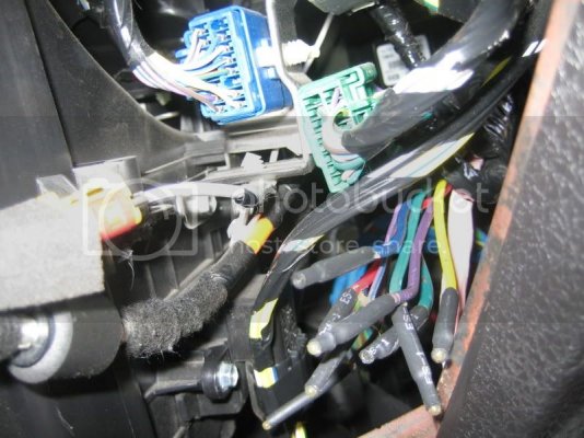
With the glovebox dropped down out of the way (empty glovebox and push both sides in so tabs clear allowing glovebox to drop down) or unbolted and removed, here is what you'll see inside looking to the right:

IMG_2884.jpg

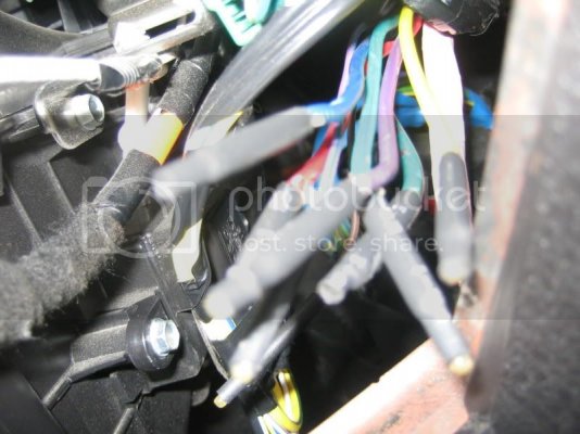
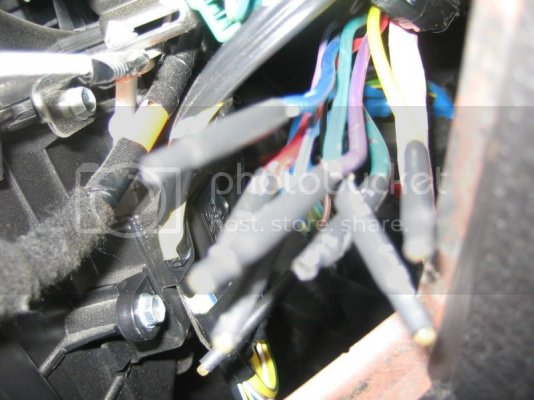
At the bottom of the above picture you can see the 8 wires you'll be looking for (the wires have black colored terminations that need to be removed and the wires stripped for connection).

Here's a close-up picture of the wires that run from the 4 Upfitter switches and the 4 wires that run under the hood near the top of the passenger fender liner. These wires need to be connected (solder or crimp connectors, etc.):

IMG_2885.jpg

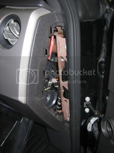
Here's a view of the removable panel (removed in this pic) at the end of the instrument panel on the passenger's side. Insert your fingers into the round A/C vent hole and pull outward towards the door and the panel will pop open.

IMG_2883.jpg
 

MagicMtnDan

FRF Addict
Joined
Oct 28, 2011
Posts
7,661
Reaction score
1,795
Location
Magic Mountain
Under the hood - locating the end of the Upfitter switch wires:

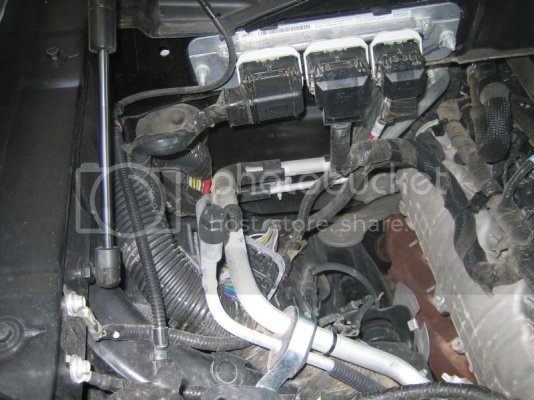
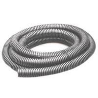
This picture was taken standing next to the front passenger side tire with the hood open looking in. To aid in orientation, notice the hood strut location and the engine. On top of the fender liner is a large protective flex tube cable manager containing a bundle of wires it looks like this:

3472487.jpg

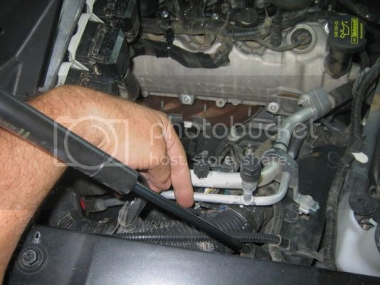
In the picture below I am pointing to the flex tube which has the wires taped to it:

IMG_2909.jpg

You can't see it in the above picture but the 4 wires from the glovebox area are taped (at the factory) to the outside of this wire protection tube. Look closely and you'll see them (you'll probably need to stand on a bucket or step stool to enable you to get a closer look at this area on top of the fender liner.

In the picture below we're looking from the front of the Raptor - you can see the firewall in the back of the picture and the left hood strut on the left side of the picture. Look at the flex tube where the wires are located - you should be able to see the color of the wires:

IMG_2908.jpg

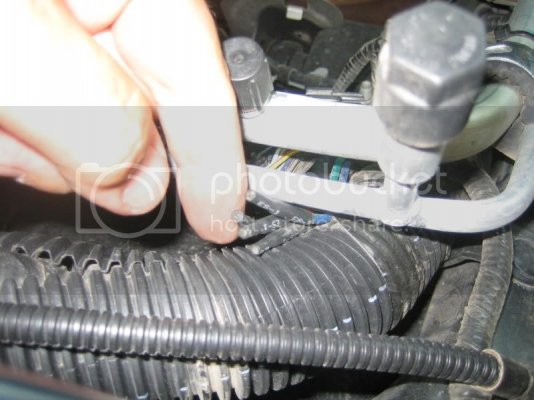
In this picture below you can see the wires taped to the flex tube:

IMG_2910.jpg

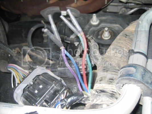
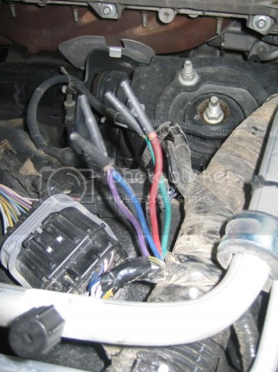
And here are the wires after I un-taped them and pulled them up away from the flex tube they are taped to:

IMG_2911.jpg

IMG_2912.jpg
 

MagicMtnDan

FRF Addict
Joined
Oct 28, 2011
Posts
7,661
Reaction score
1,795
Location
Magic Mountain
I completed the installation of the E-Series LED lights from Rigid Industries yesterday.

I had previously done the mechanical installation of the lights (as noted above) and all that remained was to make the electrical connections. I took my time as I wanted to make sure I understood the wiring in the Raptor from the factory and how I was going to connect everything.

While the Rigid Industries installation instructions are quite good I still found them lacking in regard to clarity. I'm sure my need to understand it completely first caused me to study them in detail. In any case, I got it done and everything worked the first time so it's all good.

Here is some information you might find helpful if you're installing these great Rigid Industries lights or any other devices to your 4 factory-supplied Upfitter Switches:

Notes:

1. After I installed the lights and prior to running the wires from them to the wires for the switches (Rigid Industries provides some very nice wiring harnesses), I identified which wires on the Dually harness were which and I put a piece of tape around the wires that were for the outer Duallys (at both ends of the harness). This enabled me to connect the wires to the inner and outer Dually lights when I was under the truck and connect the other ends of the wires to the underhood wires coming from the switches.

2. Ford decided to give us these great switches but not run the wires all the way underhood. Instead they ran the wires from the switches to the area behind the glovebox. They also provided us with wires from this behind-the-glovebox-area to an easy-to-access location under the hood just above the passenger side fender liner. The wires from the switches need to be connected to the wires going under the hood. Unfortunately, these connections need to be made in the area behind the glovebox. Ford gave us very little wire to work with in this area and it makes what could be a very simple task much more challenging than it needs to be.

3. You can hook up the wires from the switches to the wires under the hood any way you want as long as you consider the needs of your electrical devices and the power provided by each circuit. If you follow my connections (which I believe are the same as Rigid's instructions) you still have the option of connecting lights and other devices to any of the four underhood wires (Red, Green, Blue, Purple colored wires).

Amps...Upfitter Switch #...Wire Color Behind Glovebox from Switches...Wire Color Underhood
...30..............1..................Yelllow...........................................................Red
...30..............2..................Green with brown stripe.................................Green
...15..............3..................Purple with green stripe.................................Blue
...10..............4..................Brown (this is the thinnest of the 4 wires).......Purple

In my opinion the instructions provided were not as clear about the colors and making the connections of the 2 sets of wires that are grouped together in the area behind the glovebox. Perhaps others will find this helpful.

Here are the 8 wires in the area behind the glovebox. You can see the ends of all the wires have a black shrinktube termination on them. I used my wire stripper to remove much of these terminations.
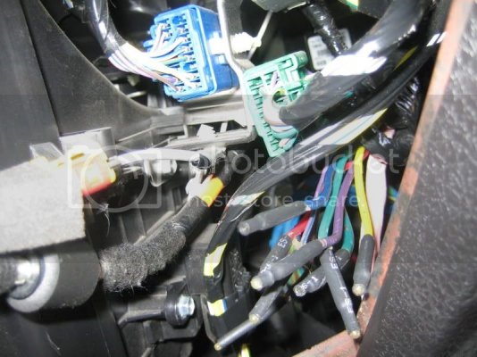
IMG_2884.jpg

Another picture of these wires:
IMG_2885.jpg
 
Top