BigJ
FRF Addict
- Joined
- Aug 5, 2010
- Posts
- 5,448
- Reaction score
- 1,561
This comes to us courtesy (reproduced here with his permission) of Dark_Wizard of F150Forum.com. These rear facing LEDs are optional on the Raptor, so this is some great info for those that didn't have them installed at the factory. Also, I think its very valuable for those of us interested in adding puddle lights (not a factory option for the Raptor), as well as for those of us interested in seeing how 'easy' it might be to add blinking LEDs to the forward facing reflector (not a factory option, period).
*********
I just finished my project and wanted to share it with everyone. I tried my best to make this as detailed as possible and easy for you to follow, some pictures like the glass removal can't be done as there wasn't enough room and light to see behind the glass let alone get a good pic.
I also didn't provide instruction on how to solder or wire splice as you should know this if you are willing to tackle this project.
I was lucky enough to have left over wiring from my Ford Remote Start/Alarm System install so my wiring is closer to the actual wiring per the diagram listed below. I have more pics in my album due to the 10 pic posting limit.
This how-to took longer for me to write than the actual project itself so I hope you enjoy it!
Please read these instructions carefully before proceeding so you have a good idea of what you are going to be doing. I would suggest you print this as well so it is by your side when doing this project. Take your time so you don't damage anything.
Note 1: I wired the mirrors for puddle lights as well even though I didn't install them on this project, just makes it easier when I'm ready. I would highly suggest doing this now even if you don't want them so it is at least there in case you change your mind down the road!
(Added by BigJ: Part number for the puddle lights is 3F1Z-13B375-AA. You'll want two of these, one for each side.)
Note 2: FYI, all the wiring (Blinkers, Heated Glass and Puddle Lights) is in the harness up to the mirror connector, you need to supply the wiring from the connector into the mirror.
Disclaimer: You are doing this at your own risk!
Project Time: 1 1/2 hours or less.
Parts List
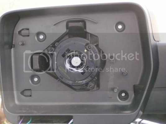
Mirror Glass Removal (Refer to figure 1.) (It is best if you have another pair of hands to make it easier but you can do this alone.)
Note: Extreme caution is advised while removing the glass. Make sure you hold the glass at all times to avoid it dropping to the pavement/concrete and breaking it!
1. Using the mirror adjust switch move the glass inwards as far as it will go until you hear the motor click, then with your flashlight look behind the glass and you will see a tab slide the screwdriver into the tab and turn until the tab releases the glass, do this for the remaining 2 tabs. Note: you need to move the glass around with the switch to get to the other tabs.
2. Repeat for other mirror.
Figure 1
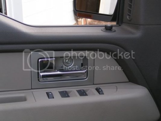
Door Panel Removal (Refer to figures 2, 2a & 2b.)
1. Remove the 2 - 6mm bolts at the bottom of the door panel.
2. Using the small flathead screwdriver remove the small square plate (where you grab to close the door) and pop it up. Remove the 8mm bolt.
3. Using the L shaped flathead screwdriver pull on the door handle and you will see a space where you can slide the screwdriver behind the black plate and give a quick pull to remove it, then remove the 8mm bolt.
4. Pull up on the door panel and out until it releases. I just let mine hang instead of disconnecting everything...the choice is yours if you want to take it completely out.
Figure 2
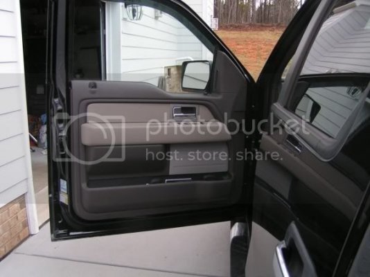
Figure 2a
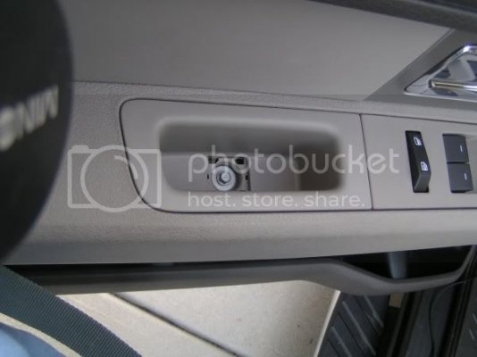
Figure 2b
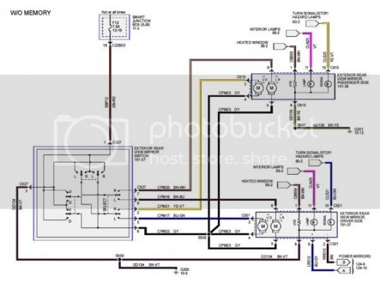
Test Wiring Harness Connections (Refer to Mirror Electrical diagram.)
1. Starting with the driver side, use the test light to verify the light lights when you turn on the blinker (key needs to be in the on position). This should be the blue w/green stripe wire, the ground from the connector should be used as well.
2. Do the same for the passenger side. (Note: There are 2 of the same wires (yellow w/violet stripe so ensure you have the correct one and mark it!)).
3. Test the puddle lights as well on both side verifying that the dome light is on.
Mirror Electrical
Mirror Removal (Refer to figure 3. - Easier to work on bench when doing the wiring.)
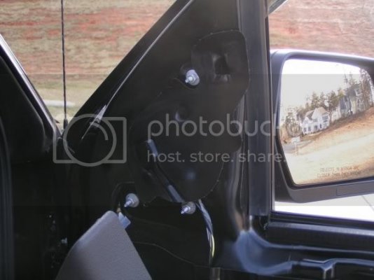
1. Remove the plastic cover near the bolts that hold the mirror onto the door, place this on your dash with sticky side up to prevent any dirt from coming in contact with it.
2. Remove the 3 - 11mm bolts using the box end wrench. The mirror is still held in by a clip on the top bolt but I would strongly urge you to hold the mirror in case the clip doesn't hold.
3. Pull the mirror assembly away from the door, remove foam pad and bring the mirror assembly to your bench (I would put something soft down first so as to not scratch your mirror assembly).
Figure 3
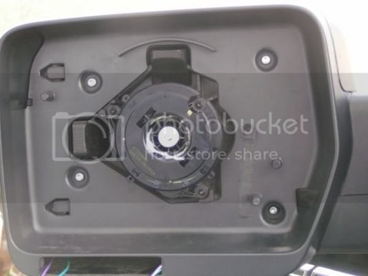
Mirror Disassembly (Refer to figures 4 & 4a)
1. Using a small flathead screwdriver remove plastic cover, this makes it easier to route your wires.
2. Using a T20 Torx screwdriver remove the 4 torx screws.
3. You will see a small tab in figure 4a at the top left of the mirror assembly, press in on the tab and gently pull the mirror apart. The mirror may not completely seperate but it will enough to route your wires.
4. Remove the dummy plates where your blinkers will go.
5. Remove the top back cover of the mirror assembly, you will need to get your fingers in there to release the 4 tabs.
Figure 4
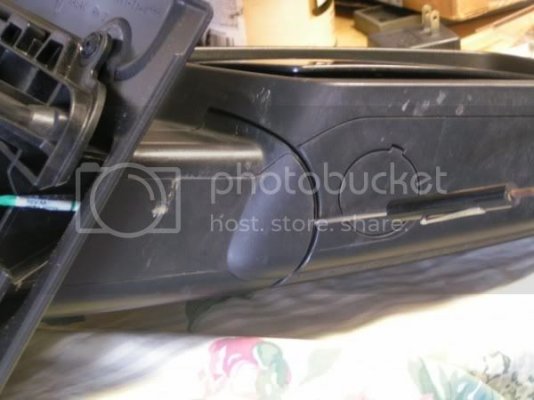
Figure 4a
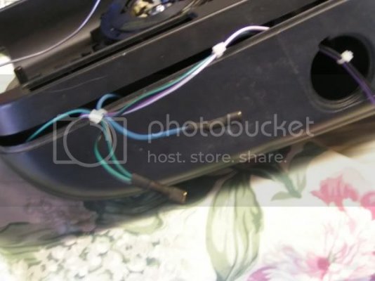
Wiring (Refer to figures 5, 5a & 5b)
1. Cut 3 wires (different color for each) approx 18" long.
2. Strip each wire on one end and insert into terminal then solder.
3. Route your wires through the mirror assembly.
4. Cut 3 pieces of shrink tubing and place over terminals and wire and then shrink them with a lighter, this is to prevent the terminals from shorting against each other as you can see how close they are on the blinker assembly.
5. Tie wrap new wires to blue wiring harness in mirror assembly.
6. finish routing wires through appropriate openings.
Figure 5
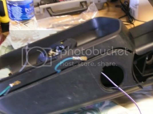
Figure 5a
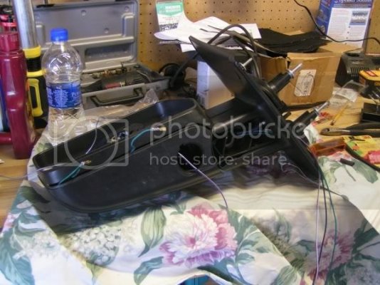
Figure 5b
Final Assembly & testing (Refer to figures 6, 6a & Final)
1. Re-assemble the mirrors and put back foam pad then mount the mirrors back on your truck while routing the new wires next to the connector and through the square hole in the door.
2. Reconnect the connectors from mirror to door harness.
3. Splice the wires into the door harness as outlined in the Mirror Electrical diagram. (I would suggest soldering them to prevent connections issues down the road).
4. Connect the LED blinkers to the wiring. Negative is the outside connector and positive is the inside. DO NOT PUT THE LED BLINKERS INTO THE MIRROR AT THIS POINT!
5. Put your key to the on postition and test each LED blinker and see that it is working correctly, if not reverse the terminals on the blinker and try again. If this still fails check your wiring and if all checks out then you have a bad blinker.
6. Once the blinkers have been tested and are confirmed working push them into the slots on the mirrors.
7. Place the plastic cover that you put on your dash back into place.
8. Reinstall door panels.
9. Reinstall glass.
Figure 6
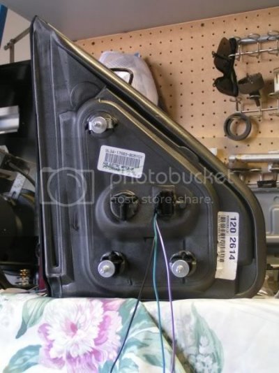
Figure 6a
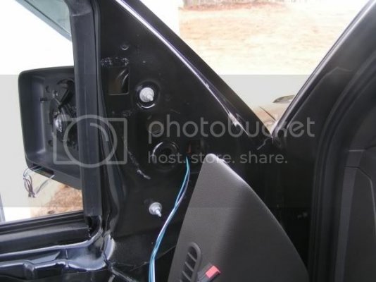
Final
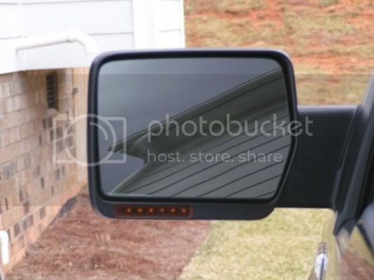
Done! Sit back grab a cold one and enjoy the fruits of your labor!
*********
I just finished my project and wanted to share it with everyone. I tried my best to make this as detailed as possible and easy for you to follow, some pictures like the glass removal can't be done as there wasn't enough room and light to see behind the glass let alone get a good pic.
I also didn't provide instruction on how to solder or wire splice as you should know this if you are willing to tackle this project.
I was lucky enough to have left over wiring from my Ford Remote Start/Alarm System install so my wiring is closer to the actual wiring per the diagram listed below. I have more pics in my album due to the 10 pic posting limit.
This how-to took longer for me to write than the actual project itself so I hope you enjoy it!
Please read these instructions carefully before proceeding so you have a good idea of what you are going to be doing. I would suggest you print this as well so it is by your side when doing this project. Take your time so you don't damage anything.
Note 1: I wired the mirrors for puddle lights as well even though I didn't install them on this project, just makes it easier when I'm ready. I would highly suggest doing this now even if you don't want them so it is at least there in case you change your mind down the road!
(Added by BigJ: Part number for the puddle lights is 3F1Z-13B375-AA. You'll want two of these, one for each side.)
Note 2: FYI, all the wiring (Blinkers, Heated Glass and Puddle Lights) is in the harness up to the mirror connector, you need to supply the wiring from the connector into the mirror.
Disclaimer: You are doing this at your own risk!
Project Time: 1 1/2 hours or less.
Parts List
- Right Side LED Blinker: Ford Part # 7L3Z-13B374-A
- Left Side LED Blinker: Ford Part # 7L3Z-13B375-A
- 3 spools of 20-22ga wire (3 different colors are needed - your choice on colors.)
- Audio Crimp Terminals (Red) (Advance Auto Parts Number - 84540 these are small terminals to fit on the LED connectors.)
- Shrink tubing (To cover the terminals above to prevent shorting.)
- Tie wraps (small)
- Small flashlight
- Long shaft flathead screwdriver (For glass removal)
- Small flathead srewdriver
- L shaped flathead screwdriver or similar device (Needed to remove the black plate behind the door handle.)
- 11mm box end wrench
- T20 Torx Driver
- 8mm x 1/4" socket
- 6mm x 1/4" socket
- 6" x 1/4" extension
- 1/4" ratchet
- 12VDC Test light
- Razor Knife
- Wire Strippers
- Electrical Tape
- Solder & Soldering Iron (only if your **** like me and want to solder your connections but I would advise you to do so.)
- Lighter (Used on shrink tubing)
Mirror Glass Removal (Refer to figure 1.) (It is best if you have another pair of hands to make it easier but you can do this alone.)
Note: Extreme caution is advised while removing the glass. Make sure you hold the glass at all times to avoid it dropping to the pavement/concrete and breaking it!
1. Using the mirror adjust switch move the glass inwards as far as it will go until you hear the motor click, then with your flashlight look behind the glass and you will see a tab slide the screwdriver into the tab and turn until the tab releases the glass, do this for the remaining 2 tabs. Note: you need to move the glass around with the switch to get to the other tabs.
2. Repeat for other mirror.
Figure 1

Door Panel Removal (Refer to figures 2, 2a & 2b.)
1. Remove the 2 - 6mm bolts at the bottom of the door panel.
2. Using the small flathead screwdriver remove the small square plate (where you grab to close the door) and pop it up. Remove the 8mm bolt.
3. Using the L shaped flathead screwdriver pull on the door handle and you will see a space where you can slide the screwdriver behind the black plate and give a quick pull to remove it, then remove the 8mm bolt.
4. Pull up on the door panel and out until it releases. I just let mine hang instead of disconnecting everything...the choice is yours if you want to take it completely out.
Figure 2

Figure 2a

Figure 2b

Test Wiring Harness Connections (Refer to Mirror Electrical diagram.)
1. Starting with the driver side, use the test light to verify the light lights when you turn on the blinker (key needs to be in the on position). This should be the blue w/green stripe wire, the ground from the connector should be used as well.
2. Do the same for the passenger side. (Note: There are 2 of the same wires (yellow w/violet stripe so ensure you have the correct one and mark it!)).
3. Test the puddle lights as well on both side verifying that the dome light is on.
Mirror Electrical

Mirror Removal (Refer to figure 3. - Easier to work on bench when doing the wiring.)
1. Remove the plastic cover near the bolts that hold the mirror onto the door, place this on your dash with sticky side up to prevent any dirt from coming in contact with it.
2. Remove the 3 - 11mm bolts using the box end wrench. The mirror is still held in by a clip on the top bolt but I would strongly urge you to hold the mirror in case the clip doesn't hold.
3. Pull the mirror assembly away from the door, remove foam pad and bring the mirror assembly to your bench (I would put something soft down first so as to not scratch your mirror assembly).
Figure 3

Mirror Disassembly (Refer to figures 4 & 4a)
1. Using a small flathead screwdriver remove plastic cover, this makes it easier to route your wires.
2. Using a T20 Torx screwdriver remove the 4 torx screws.
3. You will see a small tab in figure 4a at the top left of the mirror assembly, press in on the tab and gently pull the mirror apart. The mirror may not completely seperate but it will enough to route your wires.
4. Remove the dummy plates where your blinkers will go.
5. Remove the top back cover of the mirror assembly, you will need to get your fingers in there to release the 4 tabs.
Figure 4

Figure 4a

Wiring (Refer to figures 5, 5a & 5b)
1. Cut 3 wires (different color for each) approx 18" long.
2. Strip each wire on one end and insert into terminal then solder.
3. Route your wires through the mirror assembly.
4. Cut 3 pieces of shrink tubing and place over terminals and wire and then shrink them with a lighter, this is to prevent the terminals from shorting against each other as you can see how close they are on the blinker assembly.
5. Tie wrap new wires to blue wiring harness in mirror assembly.
6. finish routing wires through appropriate openings.
Figure 5

Figure 5a

Figure 5b

Final Assembly & testing (Refer to figures 6, 6a & Final)
1. Re-assemble the mirrors and put back foam pad then mount the mirrors back on your truck while routing the new wires next to the connector and through the square hole in the door.
2. Reconnect the connectors from mirror to door harness.
3. Splice the wires into the door harness as outlined in the Mirror Electrical diagram. (I would suggest soldering them to prevent connections issues down the road).
4. Connect the LED blinkers to the wiring. Negative is the outside connector and positive is the inside. DO NOT PUT THE LED BLINKERS INTO THE MIRROR AT THIS POINT!
5. Put your key to the on postition and test each LED blinker and see that it is working correctly, if not reverse the terminals on the blinker and try again. If this still fails check your wiring and if all checks out then you have a bad blinker.
6. Once the blinkers have been tested and are confirmed working push them into the slots on the mirrors.
7. Place the plastic cover that you put on your dash back into place.
8. Reinstall door panels.
9. Reinstall glass.
Figure 6

Figure 6a

Final

Done! Sit back grab a cold one and enjoy the fruits of your labor!

