KaiserM715
Kaiser Söze
I was given the opportunity to try out the upper control arms and tie-rods from ReadyLift. I have been keeping my eye on their products for a while, so I jumped on the chance.
Product Details
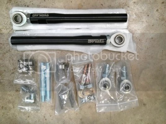
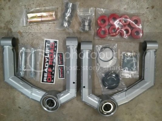
Here are the links to the products on ReadyLift’s site and pic showing what the kits include:
Tie-rods:
Ford Raptor SVT 4WD Steering Kit
Comments:
The tie-rods are pretty similar to other offerings on the market. They are made in the US and are black anodized Al with the ReadyLift logo laser etched. Fit and finish on the parts were great.
UCAs:
Uniball Upper Control Arm - 2009-2013 Ford Raptor SVT
Comments:
The UCAs are made in the US from fabricated plate and use a 1.5” spherical bearing and are compatible with the stock wheels (note: there is about 0.25” clearance between the uni ball cup and the tire sidewall – refer to pic below). It also has a low profile cap that seals the upper part of the uniball. Fit and finish on the parts were great with nice welds.
Tools
I did the install myself and will be covering some of the details as we go along. The instructions included with both kits were not Raptor specific, so I will only cover tips and items not covered there.
Tool list beyond standard hand tools:
· 21 mm socket
· 21 mm wrench
· Large pipe wrench or large Channel Locks
· 27 mm socket
· 30 mm socket
· Impact wrench capable of 400 ft-lbs
· C-Clamp
· Ratchet straps
Additional Accessories
As Houston has a fairly wet climate, I also wanted to try to extend the life of the rod ends. I came across some rod end boots from Seals-it and will give them a try. I have heard that they keep dirt and dust out pretty well, but have also heard that they may trap moisture. I will keep an eye on them and report back.
The link to the Seals-It site is below. I ordered the RERS 4 and they come in a pack of 6
Seals-It
Pre-Assembly
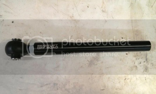
I removed the outer rod-end and installed the boot. It was a little more work than I expected…
Tie-rod w/ boot:
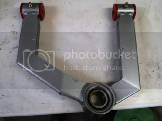
Next, I assembled the bushings and grease zerks into the UCA. The bushings popped right in, but I had to use a c-clamp to get the inner sleeve into the bushings (after they were lubricated with the included grease).
UCA assembled:
Install
Before:
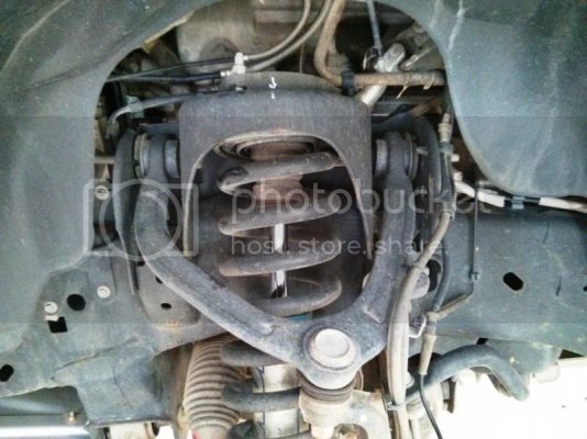
General notes:
I disconnected the brackets for brake lines, vacuum lines and wheel speed sensors to get a little extra slack. I also used a couple of ratchet straps to keep the knuckle from flopping around and causing damage to the previously mentioned lines. Everything that attaches to the factory mounting / attach points should be torqued to the factory values, which can be found here: http://www.fordraptorforum.com/f39/torque-specs-11451/ As I don’t do this every day, this job took me from about noon to dark on one day with about 1 hour of finish up the next. I think I could have shaved off a couple of hours (refer below), but I would still plan for most of a day if you are doing this job by yourself.
Tie-rod removal:
The “nut” that goes into the rack is very large (larger than any wrench I have), so the other two options are to use a large pair of Channel Locks (on the flats) or a large pipe wrench on the O.D. I used a pipe wrench. I measured the length of the stock tie-rods and then adjusted the new tie-rods to match. Then disassemble the stockers to remove the boot. You can also get new boots from Rock Auto for $12 each (RAYBESTOS Part # 4301132). Trim the boots as directed and install on the new units.
Tie-rod installation:
When you install the bolt into the rack USE HIGH STRENGTH LOC-TITE!! I have heard several recommendations to torque the bolt to 150 ft-lbs. I tried to do this and almost stripped the bolt. I consulted with ReadyLift and they recommended the stock value of 89 ft-lbs and to USE HIGH STRENGTH LOC-TITE!!
UCA removal:
Be careful removing the Christmas tree connector for the vacuum lines from the stock UCA as it is easy to break them. Note the zip tie around the new UCA in the pic below. I consulted with several sources, some of which said that the bolts for the UCAs can be removed without pulling the shock. I banged my head against the wall for a couple of hours trying this method to no avail. Based on what I saw, the CV shaft prevents the LCA from drooping far enough for this to work. Once I pulled the shock the remainder of the job was a breeze. The first step is to support the suspension with a jack. Then remove the three nuts from the cast iron ring on top of the shock tower (mark it for orientation, it only goes back together correctly one way). Let the jack down and remove the lower shock nut and bolt. Slide the shock up, pull the bottom out and set it aside. A note about pulling the shock: you will need a pretty healthy impact to get the nut loose.
UCA installation:
Reverse of removal I also used this opportunity to give my front shocks another coat of BoeShield (a little more HERE). To reinstall the lower shock bolt, I hammered on it with my impact wrench until it wouldn’t move (it is rated for 400 ft-lb). I have a 30 mm ¾” drive socket coming to use with my ¾” breaker bar with a cheater pipe for final tightening.
During:
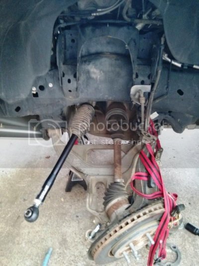
This gives you an idea of how much work is required to get everything out of the way.
Finished:
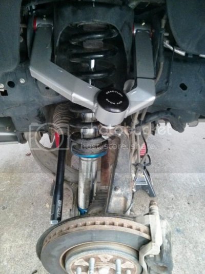
Here is a pic showing the clearance between the uniball cup and the tire:
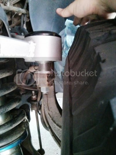
Rack Bellows / Boot:
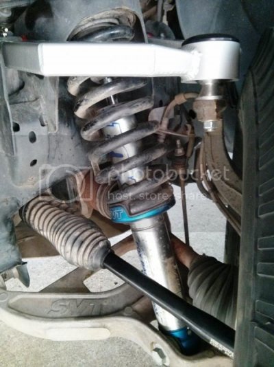
This turned out to be an issue that was a little harder to solve than I anticipated. I contacted some others on ways to re-secure the boots and got some good suggestions. I used a big hose clamp to secure the boot to the rack and that works great (as suggested by Joe). The main issue is with the other end. The instructions recommend cutting the end of the boot for the tie-rod to fit. BigJ's solution was to heat the boots and stretch them - which I think is the better solution. I was able to get a zip tie to hang on to the end where I cut (you can make it out in the pic below). The other issue is that the threaded end of the clevis bolt grabs the pleats and pulls the boot. You can see where that has happened below as all of the pleats are stretched out on the top. I am not sure what to do long term, but this will work for now.
Alignment:
The geometry of the ReadyLift UCAs is slightly different, giving my truck a slight positive camber and the tie-rods were just “close enough”(my steering wheel was off-center) – and alignment is DEFINITELY recommended. Here is what I requested and what I wound up with: http://www.fordraptorforum.com/f9/your-raptor-its-alignment-539/index21.html#post715301
On-Road Driving Impressions:
It is obvious that these parts are significantly beefier than stock. That being said, I think this is a very subjective area. I want to think that the front end feels more solid, but it not something that is dramatically noticeable to me. I have only driven it a couple of days, so I will update as needed.
Off-Road Driving Impressions:
I will have to update this after I get my truck in the dirt.
Overall:
I am very pleased with the upgrades and installing them wasn't bad at all, once I decided to pull the shocks. I can't wait to try them in the dirt.
To Do:
Long term solution to rack bellows / boot.
Product Details
Here are the links to the products on ReadyLift’s site and pic showing what the kits include:
Tie-rods:
Ford Raptor SVT 4WD Steering Kit

Comments:
The tie-rods are pretty similar to other offerings on the market. They are made in the US and are black anodized Al with the ReadyLift logo laser etched. Fit and finish on the parts were great.
UCAs:
Uniball Upper Control Arm - 2009-2013 Ford Raptor SVT

Comments:
The UCAs are made in the US from fabricated plate and use a 1.5” spherical bearing and are compatible with the stock wheels (note: there is about 0.25” clearance between the uni ball cup and the tire sidewall – refer to pic below). It also has a low profile cap that seals the upper part of the uniball. Fit and finish on the parts were great with nice welds.
Tools
I did the install myself and will be covering some of the details as we go along. The instructions included with both kits were not Raptor specific, so I will only cover tips and items not covered there.
Tool list beyond standard hand tools:
· 21 mm socket
· 21 mm wrench
· Large pipe wrench or large Channel Locks
· 27 mm socket
· 30 mm socket
· Impact wrench capable of 400 ft-lbs
· C-Clamp
· Ratchet straps
Additional Accessories
As Houston has a fairly wet climate, I also wanted to try to extend the life of the rod ends. I came across some rod end boots from Seals-it and will give them a try. I have heard that they keep dirt and dust out pretty well, but have also heard that they may trap moisture. I will keep an eye on them and report back.
The link to the Seals-It site is below. I ordered the RERS 4 and they come in a pack of 6
Seals-It
Pre-Assembly
I removed the outer rod-end and installed the boot. It was a little more work than I expected…
Tie-rod w/ boot:

Next, I assembled the bushings and grease zerks into the UCA. The bushings popped right in, but I had to use a c-clamp to get the inner sleeve into the bushings (after they were lubricated with the included grease).
UCA assembled:

Install
Before:

General notes:
I disconnected the brackets for brake lines, vacuum lines and wheel speed sensors to get a little extra slack. I also used a couple of ratchet straps to keep the knuckle from flopping around and causing damage to the previously mentioned lines. Everything that attaches to the factory mounting / attach points should be torqued to the factory values, which can be found here: http://www.fordraptorforum.com/f39/torque-specs-11451/ As I don’t do this every day, this job took me from about noon to dark on one day with about 1 hour of finish up the next. I think I could have shaved off a couple of hours (refer below), but I would still plan for most of a day if you are doing this job by yourself.
Tie-rod removal:
The “nut” that goes into the rack is very large (larger than any wrench I have), so the other two options are to use a large pair of Channel Locks (on the flats) or a large pipe wrench on the O.D. I used a pipe wrench. I measured the length of the stock tie-rods and then adjusted the new tie-rods to match. Then disassemble the stockers to remove the boot. You can also get new boots from Rock Auto for $12 each (RAYBESTOS Part # 4301132). Trim the boots as directed and install on the new units.
Tie-rod installation:
When you install the bolt into the rack USE HIGH STRENGTH LOC-TITE!! I have heard several recommendations to torque the bolt to 150 ft-lbs. I tried to do this and almost stripped the bolt. I consulted with ReadyLift and they recommended the stock value of 89 ft-lbs and to USE HIGH STRENGTH LOC-TITE!!
UCA removal:
Be careful removing the Christmas tree connector for the vacuum lines from the stock UCA as it is easy to break them. Note the zip tie around the new UCA in the pic below. I consulted with several sources, some of which said that the bolts for the UCAs can be removed without pulling the shock. I banged my head against the wall for a couple of hours trying this method to no avail. Based on what I saw, the CV shaft prevents the LCA from drooping far enough for this to work. Once I pulled the shock the remainder of the job was a breeze. The first step is to support the suspension with a jack. Then remove the three nuts from the cast iron ring on top of the shock tower (mark it for orientation, it only goes back together correctly one way). Let the jack down and remove the lower shock nut and bolt. Slide the shock up, pull the bottom out and set it aside. A note about pulling the shock: you will need a pretty healthy impact to get the nut loose.
UCA installation:
Reverse of removal
 I also used this opportunity to give my front shocks another coat of BoeShield (a little more HERE). To reinstall the lower shock bolt, I hammered on it with my impact wrench until it wouldn’t move (it is rated for 400 ft-lb). I have a 30 mm ¾” drive socket coming to use with my ¾” breaker bar with a cheater pipe for final tightening.
During:

This gives you an idea of how much work is required to get everything out of the way.
Finished:

Here is a pic showing the clearance between the uniball cup and the tire:

Rack Bellows / Boot:
This turned out to be an issue that was a little harder to solve than I anticipated. I contacted some others on ways to re-secure the boots and got some good suggestions. I used a big hose clamp to secure the boot to the rack and that works great (as suggested by Joe). The main issue is with the other end. The instructions recommend cutting the end of the boot for the tie-rod to fit. BigJ's solution was to heat the boots and stretch them - which I think is the better solution. I was able to get a zip tie to hang on to the end where I cut (you can make it out in the pic below). The other issue is that the threaded end of the clevis bolt grabs the pleats and pulls the boot. You can see where that has happened below as all of the pleats are stretched out on the top. I am not sure what to do long term, but this will work for now.

Alignment:
The geometry of the ReadyLift UCAs is slightly different, giving my truck a slight positive camber and the tie-rods were just “close enough”(my steering wheel was off-center) – and alignment is DEFINITELY recommended. Here is what I requested and what I wound up with: http://www.fordraptorforum.com/f9/your-raptor-its-alignment-539/index21.html#post715301
On-Road Driving Impressions:
It is obvious that these parts are significantly beefier than stock. That being said, I think this is a very subjective area. I want to think that the front end feels more solid, but it not something that is dramatically noticeable to me. I have only driven it a couple of days, so I will update as needed.
Off-Road Driving Impressions:
I will have to update this after I get my truck in the dirt.
Overall:
I am very pleased with the upgrades and installing them wasn't bad at all, once I decided to pull the shocks. I can't wait to try them in the dirt.
To Do:
Long term solution to rack bellows / boot.
Last edited:


