bigrig
Full Access Member
Installing a 50 Watt VHF Vertex VX2200
After reading one of the prerequisites for joining Raptor Expeditions on their Barstow to Vegas run was to install a 50 watt 2-way radio, I started looking around for one to install. I am no ham radio expert and really have only had experience with the citizen band, but Rugged Radios had a package that looked complete (Car to Car Kit with PTT - VHF Vertex VX2200 50 Watt) and it was on sale ($445.61) so I went for it.
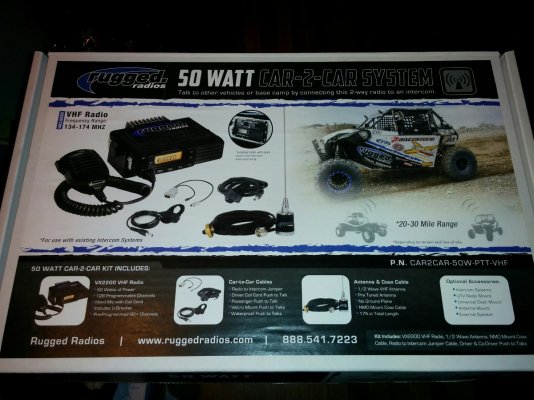
The radio arrived relatively quickly and in good condition. I spent part of this weekend installing it with relative success. The temperatures here today were in the low 40s (that is super freezing for a California kid) so I may have rushed parts of the install where I would normally like to take my time. Overall it turned out pretty good so I wanted to share my experience in hopes it may help others out.
Tools I used:
Installing the Antenna Base:
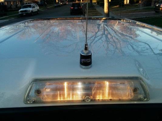
I decided to mount the antenna on the angled part of the roof near the backup/brake light. It was the strongest and least flexible part of the roof which seemed to me to be the best choice for placement. Also, the backup/brake light, once removed, provided easy access to screw in the coaxial cable.
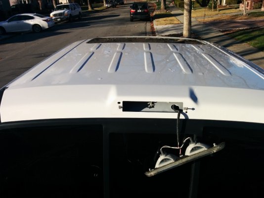
Drill Hole in Roof:
I applied masking tape to the roof and then measured a center line and used a center punch to mark the place I wanted to drill. I drilled a hole at my mark.
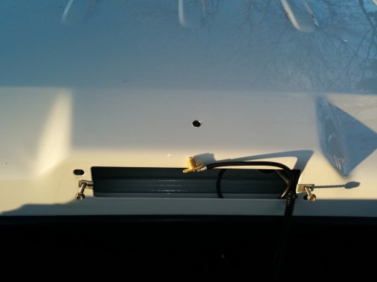
Mount the No Ground Plane Base:
This was just a matter of ******** in the top plate to the center of the base through the roof. I did notice that I had to tighten it more than I initially thought (I didn’t want to mess up the o-ring). I didn’t use crushing force but I did use more than I would have expected. I would equate it to the way it feels when you tighten an oil filter on.
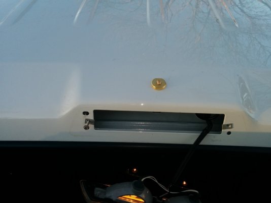
Mount the Antenna:
I mounted the antenna to test for fit and to make sure it was centered.
Optional - Cap the Antenna:
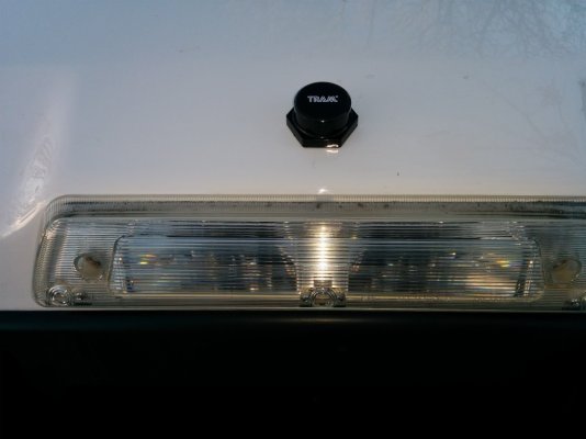
I also ordered a cap that I could place on the antenna base while the antenna wasn’t on the roof, it cost me about $6.00 after shipping.
Routing the Antenna Coaxial Cable::
First off, I flipped the switch to lower the seat so I could access the back of the cab. Then I started by removing one of the headliner retainers (these are nylon pushpins) as well as the interior plastic body panel that covers the rear passenger seatbelt. This had one bolt at the top, several pressure fittings down the body panel and a two nylon pushpins at the bottom.
Headline retainer:
I tried to be gentle with this, the nylon pushpins always get compromised every time I take them out and I am trying to get as much life out of them as I can.
Top Plastic Body Panel:
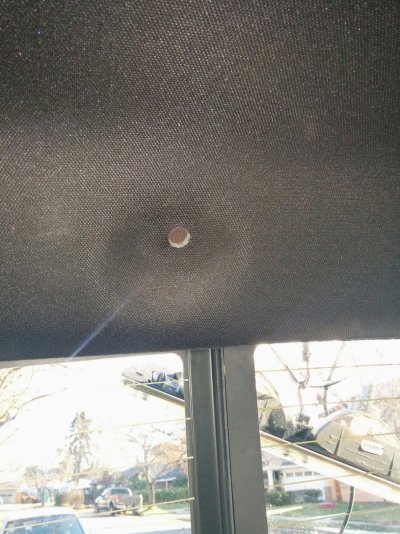
There is a bolt up at the top behind a plastic plug. The plug just pops out and the bolt can be unscrewed from there with a socket. I had to be careful not to drop the bolt down behind the body panel as it got loose.
Bottom Plastic Body Body Panel:
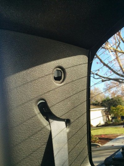
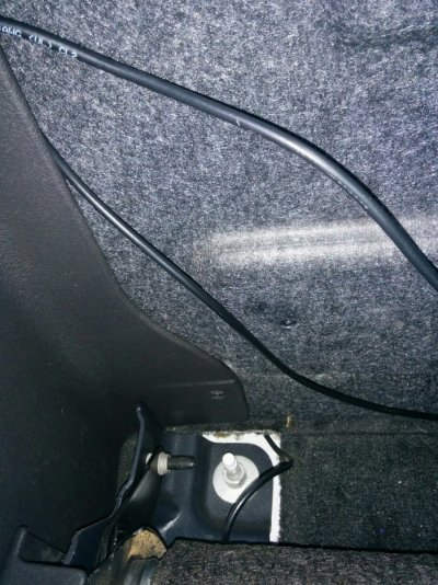
There are two nylon pushpins at the bottom. You can see where one of them was in this picture.
Get Access Behind the Body Panel:
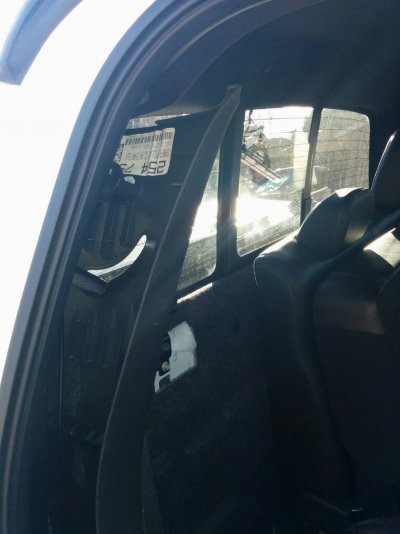
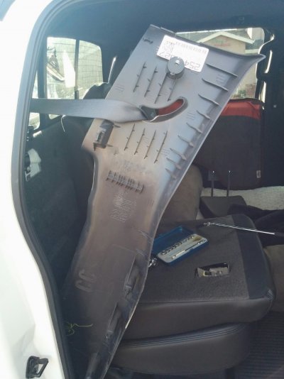
Once everything was loose I moved the body panel out a bit so I could more easily route the coaxial cable to the carpet on the floor.
Route Cable Under Carpet:
I took out the subwoofer for this next part. I removed three bolts, one on top towards the back of the cab and two at the feet towards the front of the subwoofer below the plastic covers as well as unhooking the power cable which is a plug under the subwoofer.
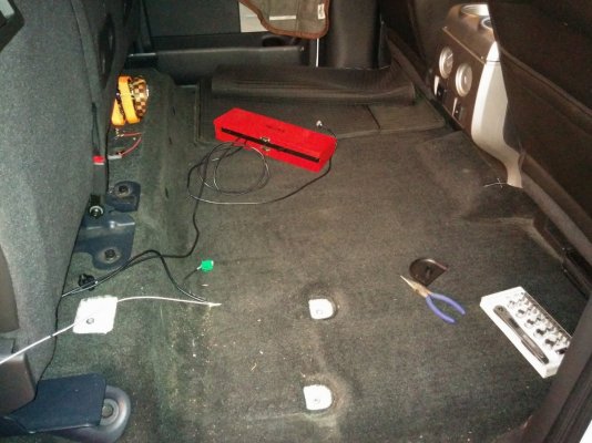
I also removed the plastic entry step pad to provide more easy access to under the carpet. I wanted to make sure I got the cable under the carpet and the matting because routing cables between the matting and the carpet is very difficult since it is pretty much glued together.
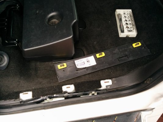
I routed the cables under the carpet using bent coat hangers and string to feed the wire where I needed it. I cut a hole in the shape of a “T” by the right rear corner of the center console. I pulled the coaxial cable through that and fed it under the center console. (to fully get the cable under the center console I had to remove two bolts at the rear of the center console. They are easily accessible when the front seats are moved forward.
Mounting the Radio::
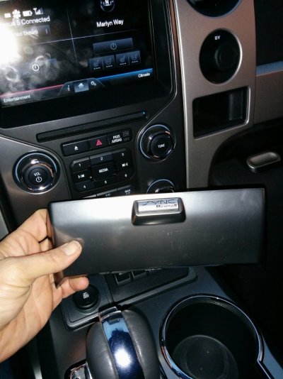
I started by removing the SYNC faceplate. This allows access to pull up the body panel with the upfitter switches and the cup holders.
Remove Upfitter/Cupholder Body Panel:
I centered the shifter by putting it in Neutral. This piece pops out pretty easily once that is done. Light pulling pressure upwards will make it pop out. I unplugged the 3 plugs under the upfitter switches to fully remove the body panel.
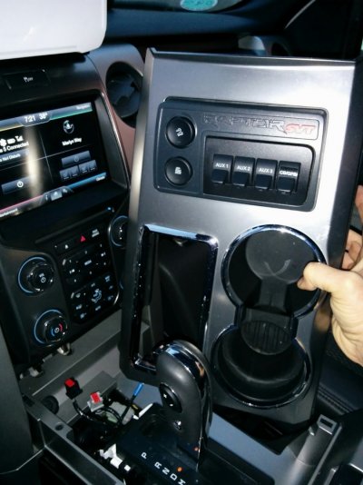
Here is a picture of the three plugs:
Unbolt the shifter:
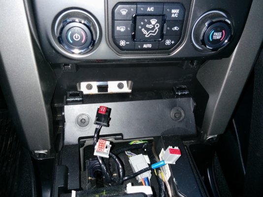
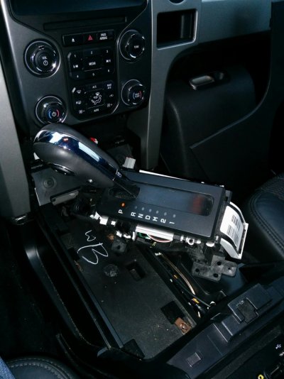
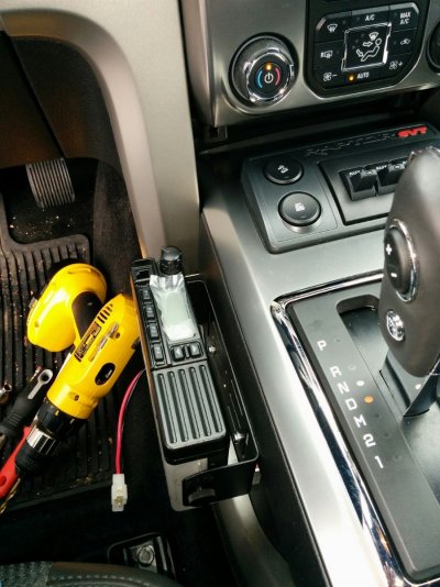
I wanted to mount my radio on the side wall of the center console, next to my right knee while I was driving. To access this wall I removed the four bolts holding down the shifter. The shifter can then be slided to the right opening up access to the side wall. I should note in the following picture more of the body paneling on the center console was removed. That isn’t necessary, I got a little gung-ho when taking everything apart.
Making the Backing Plate for Radio Mount:
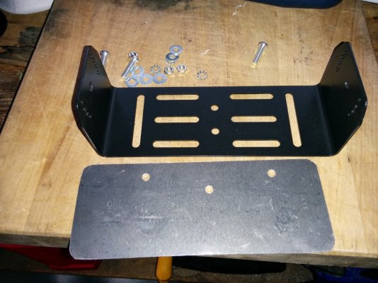
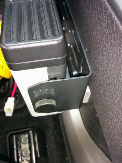
Because the plastic on the center console isn’t super strong I created an aluminum backing plate that I could slide into the inside of the center console to reinforce it. Those of you with good eyes will notice that the holes are not centered, that was where the cold got the better of me. I think my garage was about 30 degrees at that point and I rushed making this piece. But because this piece wasn’t going to be seeing the light of day anyway, I used it. I should also note that I had aspirations of mounting it in three places, but space ultimately required me to mount it in only two.
Making the Spacer Plate for Radio Mount:
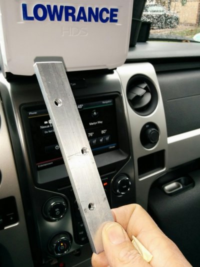
Because of the contours of the body paneling on the center console I had to create a spacer to mount in between the radio mount and the center console to provide proper clearance for the wires and to make sure the radio didn’t rattle against the center console.
Mount the Spacer, Backing Plate, and Radio Mount Together:
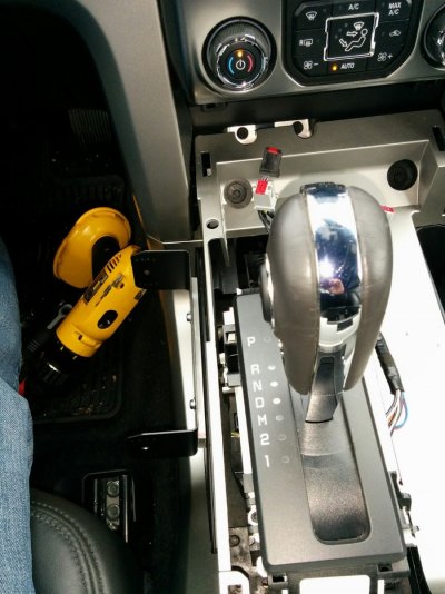
This is the whole thing put together without the radio.
Here it is with the radio mounted and with the body panels back in place:
You can see the backing plate here and how it compensates for the contours:
Wiring:
I wired the radio to the third upfitter switch (Aux 3). I drilled a hole in the silver plastic trim to route the wires through for power. I am not sure I would suggest this to anyone since doing so now requires that I disconnect the wires if I ever want to get the silver trim off. I used lever connectors that are easily accessible through the side port near the driver's right foot to make it so it wouldn’t be as cumbersome to get the trim off in the future but I am sure there are better ways of doing this.
I hope this post helps anyone trying to do this on their own. It took me about a day to complete the whole thing. Now, I just need someone to talk to
Measure twice, cut once, have fun, enjoy the process.
~bigrig
After reading one of the prerequisites for joining Raptor Expeditions on their Barstow to Vegas run was to install a 50 watt 2-way radio, I started looking around for one to install. I am no ham radio expert and really have only had experience with the citizen band, but Rugged Radios had a package that looked complete (Car to Car Kit with PTT - VHF Vertex VX2200 50 Watt) and it was on sale ($445.61) so I went for it.

The radio arrived relatively quickly and in good condition. I spent part of this weekend installing it with relative success. The temperatures here today were in the low 40s (that is super freezing for a California kid) so I may have rushed parts of the install where I would normally like to take my time. Overall it turned out pretty good so I wanted to share my experience in hopes it may help others out.
Tools I used:
- Belt Sander
- C-clamps
- Center Punch
- Crescent Wrench
- Coat Hanger
- Drill
- Files
- Jigsaw
- Magnets
- Needle Nose
- Socket Set
- Soldering Iron
- Tape Measure
- Torx Set
- Screw Drivers
- String
- Wire Stripper
Installing the Antenna Base:
I decided to mount the antenna on the angled part of the roof near the backup/brake light. It was the strongest and least flexible part of the roof which seemed to me to be the best choice for placement. Also, the backup/brake light, once removed, provided easy access to screw in the coaxial cable.

Drill Hole in Roof:
I applied masking tape to the roof and then measured a center line and used a center punch to mark the place I wanted to drill. I drilled a hole at my mark.

Mount the No Ground Plane Base:
This was just a matter of ******** in the top plate to the center of the base through the roof. I did notice that I had to tighten it more than I initially thought (I didn’t want to mess up the o-ring). I didn’t use crushing force but I did use more than I would have expected. I would equate it to the way it feels when you tighten an oil filter on.

Mount the Antenna:
I mounted the antenna to test for fit and to make sure it was centered.

Optional - Cap the Antenna:
I also ordered a cap that I could place on the antenna base while the antenna wasn’t on the roof, it cost me about $6.00 after shipping.

Routing the Antenna Coaxial Cable::
First off, I flipped the switch to lower the seat so I could access the back of the cab. Then I started by removing one of the headliner retainers (these are nylon pushpins) as well as the interior plastic body panel that covers the rear passenger seatbelt. This had one bolt at the top, several pressure fittings down the body panel and a two nylon pushpins at the bottom.
Headline retainer:
I tried to be gentle with this, the nylon pushpins always get compromised every time I take them out and I am trying to get as much life out of them as I can.

Top Plastic Body Panel:
There is a bolt up at the top behind a plastic plug. The plug just pops out and the bolt can be unscrewed from there with a socket. I had to be careful not to drop the bolt down behind the body panel as it got loose.

Bottom Plastic Body Body Panel:
There are two nylon pushpins at the bottom. You can see where one of them was in this picture.

Get Access Behind the Body Panel:
Once everything was loose I moved the body panel out a bit so I could more easily route the coaxial cable to the carpet on the floor.


Route Cable Under Carpet:
I took out the subwoofer for this next part. I removed three bolts, one on top towards the back of the cab and two at the feet towards the front of the subwoofer below the plastic covers as well as unhooking the power cable which is a plug under the subwoofer.

I also removed the plastic entry step pad to provide more easy access to under the carpet. I wanted to make sure I got the cable under the carpet and the matting because routing cables between the matting and the carpet is very difficult since it is pretty much glued together.

I routed the cables under the carpet using bent coat hangers and string to feed the wire where I needed it. I cut a hole in the shape of a “T” by the right rear corner of the center console. I pulled the coaxial cable through that and fed it under the center console. (to fully get the cable under the center console I had to remove two bolts at the rear of the center console. They are easily accessible when the front seats are moved forward.
Mounting the Radio::
I started by removing the SYNC faceplate. This allows access to pull up the body panel with the upfitter switches and the cup holders.

Remove Upfitter/Cupholder Body Panel:
I centered the shifter by putting it in Neutral. This piece pops out pretty easily once that is done. Light pulling pressure upwards will make it pop out. I unplugged the 3 plugs under the upfitter switches to fully remove the body panel.

Here is a picture of the three plugs:

Unbolt the shifter:
I wanted to mount my radio on the side wall of the center console, next to my right knee while I was driving. To access this wall I removed the four bolts holding down the shifter. The shifter can then be slided to the right opening up access to the side wall. I should note in the following picture more of the body paneling on the center console was removed. That isn’t necessary, I got a little gung-ho when taking everything apart.

Making the Backing Plate for Radio Mount:
Because the plastic on the center console isn’t super strong I created an aluminum backing plate that I could slide into the inside of the center console to reinforce it. Those of you with good eyes will notice that the holes are not centered, that was where the cold got the better of me. I think my garage was about 30 degrees at that point and I rushed making this piece. But because this piece wasn’t going to be seeing the light of day anyway, I used it. I should also note that I had aspirations of mounting it in three places, but space ultimately required me to mount it in only two.

Making the Spacer Plate for Radio Mount:
Because of the contours of the body paneling on the center console I had to create a spacer to mount in between the radio mount and the center console to provide proper clearance for the wires and to make sure the radio didn’t rattle against the center console.

Mount the Spacer, Backing Plate, and Radio Mount Together:
This is the whole thing put together without the radio.

Here it is with the radio mounted and with the body panels back in place:

You can see the backing plate here and how it compensates for the contours:

Wiring:
I wired the radio to the third upfitter switch (Aux 3). I drilled a hole in the silver plastic trim to route the wires through for power. I am not sure I would suggest this to anyone since doing so now requires that I disconnect the wires if I ever want to get the silver trim off. I used lever connectors that are easily accessible through the side port near the driver's right foot to make it so it wouldn’t be as cumbersome to get the trim off in the future but I am sure there are better ways of doing this.
I hope this post helps anyone trying to do this on their own. It took me about a day to complete the whole thing. Now, I just need someone to talk to
Measure twice, cut once, have fun, enjoy the process.
~bigrig
Last edited:

