BigJ
FRF Addict
- Joined
- Aug 5, 2010
- Posts
- 5,448
- Reaction score
- 1,561
Supporting Vendor SDHQ Offroad (click here) has put together perhaps the most comprehensive "how to" regarding adjusting the Raptor's Fox Shock perch setting. All material below is courtesy of Ryan and SDHQ, and all credit belongs to them. Great writeup guys and thanks for letting us host it here!
A couple quick notes before the writeup:
-The net result is approx 2.5" lift in the front, bringing the nose level with the rear.
-Yes, you will need an alignment done after this adjustment
-According to an SVT engineer, the factory warranty on the Fox Shock is 3 year/36k miles (click here)
-According to an SVT engineer: "[Leveling the nose via the perch adjustment described below...] It all depends on what you want to do with it. Using the detents would raise the front ride height of the truck and would give you more jounce travel, but take away rebound travel. This would really change how the truck rides and handles on and offroad especially when taking in consideration how we tuned the bypass shocks and how they ramp up damping force. This would also potentially void the warranty." (click here)
And here's SDHQ's writeup!
Here are a couple pics we snapped while we were leveling out the Raptor. Hope this helps...
Stock height before tire removal
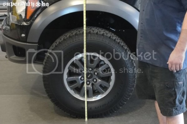
Stock height bottom of fender

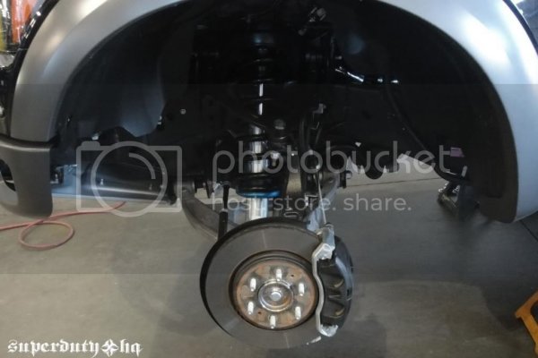
Remove tire/wheel
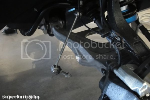
Disconnect sway bay link
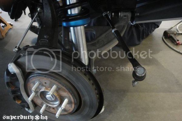
Disconnect tie rod
Remove nut on upper ball joint to remove upper control arm
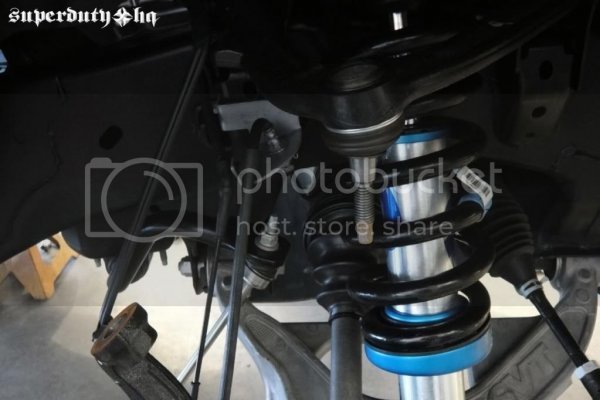
Remove upper shock bolt and lower shock bolt
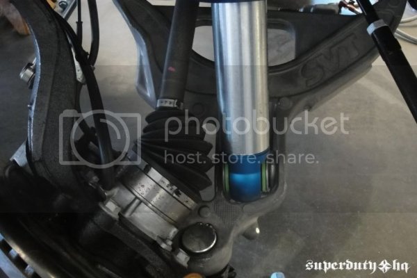
Remove shock assembly from tuck
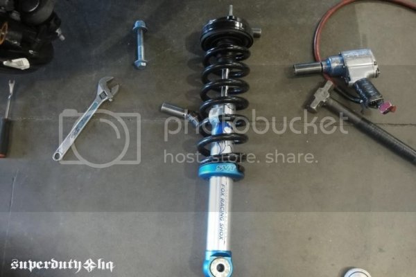
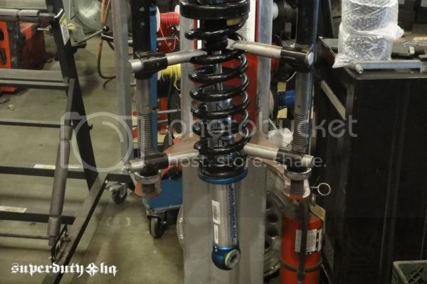
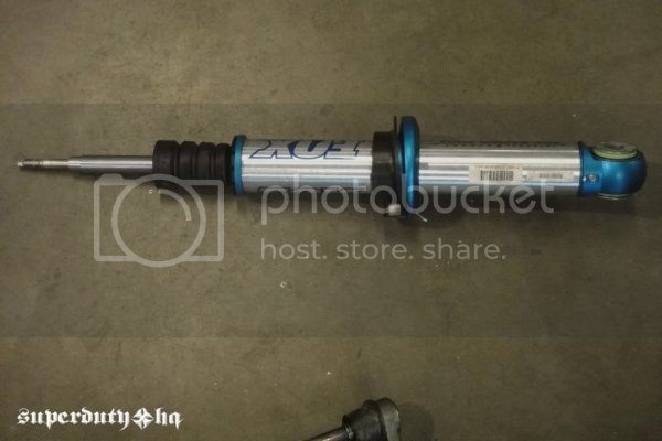
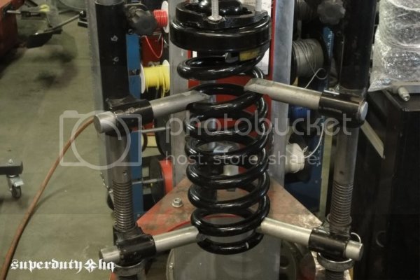
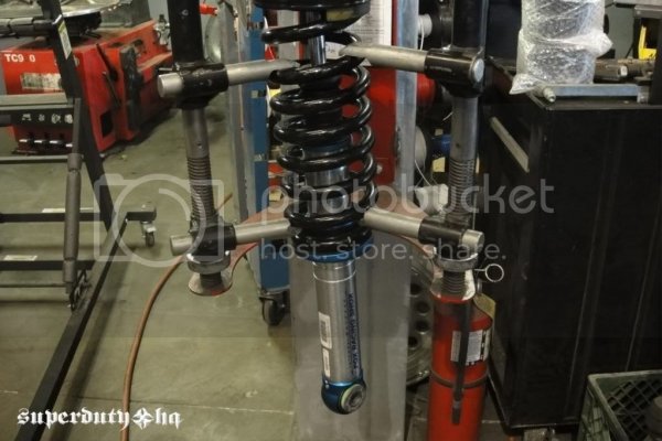
Place shock in spring compressor & remove coil spring
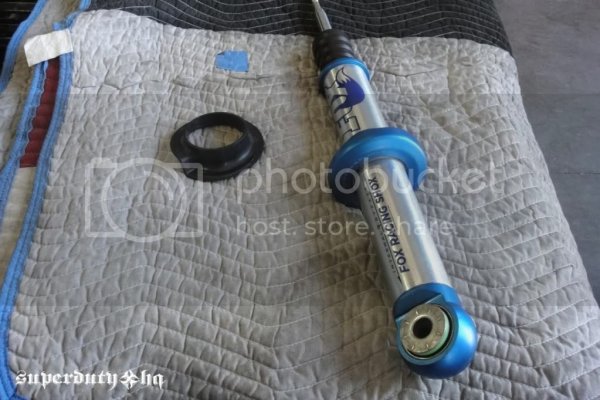
Remove set screw to move lower mount
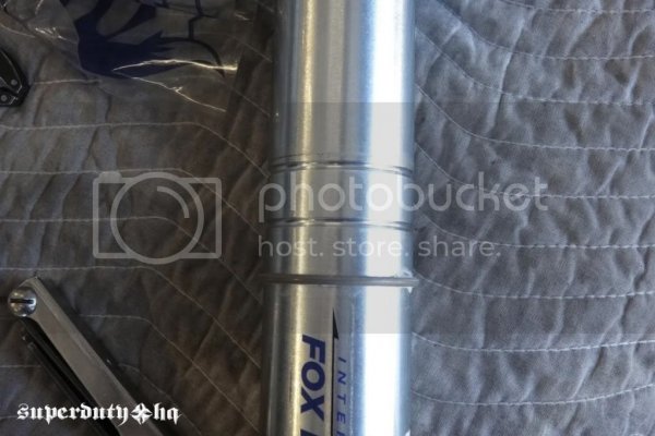
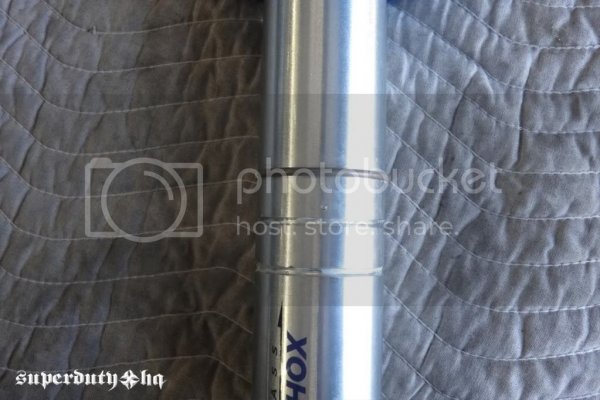
We moved the snap ring to 3rd notch for the most lift
Reassemble shock
Reinstall shock & reconnect upper control arm
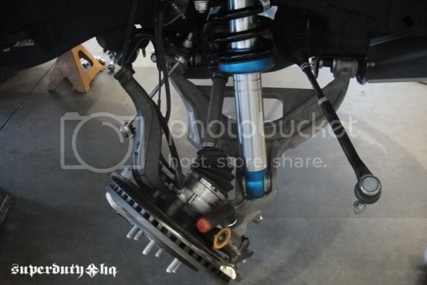
Reconnect tie rod
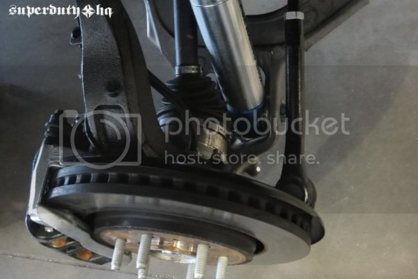
Reconnect sway bar linkage
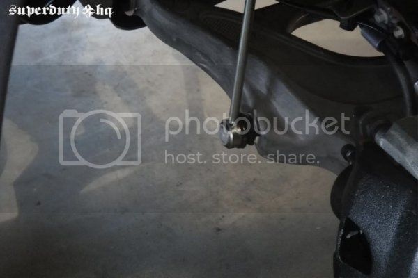
Double check all hardware, brakelines, etc.
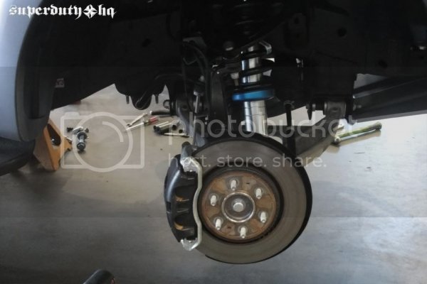
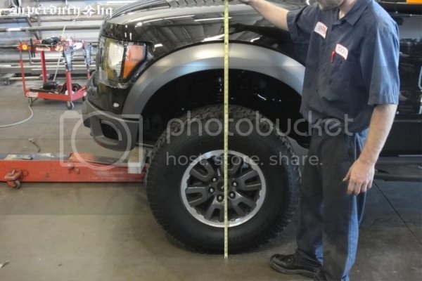
Back on the ground 2.5” higher
Check over & road test then to alignment
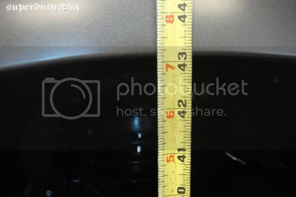
Stock
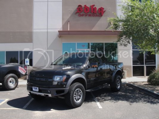
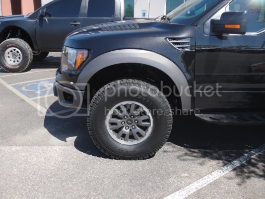
After adjustment
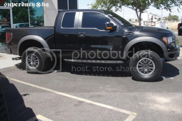
A couple quick notes before the writeup:
-The net result is approx 2.5" lift in the front, bringing the nose level with the rear.
-Yes, you will need an alignment done after this adjustment
-According to an SVT engineer, the factory warranty on the Fox Shock is 3 year/36k miles (click here)
-According to an SVT engineer: "[Leveling the nose via the perch adjustment described below...] It all depends on what you want to do with it. Using the detents would raise the front ride height of the truck and would give you more jounce travel, but take away rebound travel. This would really change how the truck rides and handles on and offroad especially when taking in consideration how we tuned the bypass shocks and how they ramp up damping force. This would also potentially void the warranty." (click here)
And here's SDHQ's writeup!
Here are a couple pics we snapped while we were leveling out the Raptor. Hope this helps...
Stock height before tire removal

Stock height bottom of fender

Remove tire/wheel

Disconnect sway bay link

Disconnect tie rod

Remove nut on upper ball joint to remove upper control arm

Remove upper shock bolt and lower shock bolt

Remove shock assembly from tuck


Place shock in spring compressor & remove coil spring

Remove set screw to move lower mount


We moved the snap ring to 3rd notch for the most lift

Reassemble shock

Reinstall shock & reconnect upper control arm

Reconnect tie rod

Reconnect sway bar linkage

Double check all hardware, brakelines, etc.


Back on the ground 2.5” higher
Check over & road test then to alignment

Stock


After adjustment

Last edited by a moderator:


